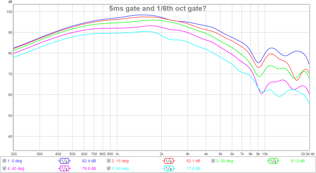
45 to 50dB disortion below your fundamental is not bad for a little 2.5in cone driver at 95dB. Looks like XO at 500Hz should keep all that mush in the lower frequencies out. What high pass filter are you running? Can you put a BW2 350Hz HPF and see what HD looks like?
Make sure you start wearing earplugs for full level sweeps...")
Make sure you start wearing earplugs for full level sweeps...


Right I gotta go now - or my wife will leave me. Lots more to do to optimize things. That was just a quick EQ I did - I reckon I can improve on it. Measurement were made in poor environment in my study etc. etc.
Over this weekend I will likely start on the woofer platforms, gaskets and taps. I am quite excited that this could really pan out well.
I spent ages looking at horn data and had already decided that the XT1464 looked like the best cheap CD horn with good polars.
It was then the recent full-range drivers used on horns that XrK experimented with that inspired me to try the SB65 on the XT1464.
I was thinking about using a 10f - but was worried about the 3inch driver transitioning into the 1.4inch throat. The 2.5" SB65 seems to have been just right.
I then planned on doing a synergy but frankly it would have taken me months to get to grips with the softwear, so XrK (and Brytt) have been utterly invaluable with all the modelling etc.
I am starting to get excited now that this could actually pan out rather well....
I will keep you posted as I make more progress with the build!
I was just about to mention that. I would also love to see a frequency + phase plot with that same frequency dependant filter set. The dip is acting the same over all angles, lets see what phase does there.
So does a phase plot like this mean my uTrynergy is working well phase wise up to 8kHz over a 45 deg half angle? Greater than 45 deg and it falls apart, and greater than 8kHz it falls apart coherency wise?

This is the corresponding gated frequency response:
Really interesting thread that is moving very fast!
I can buy a couple of these waveguides for a good price if I add them onto another order I will be making soon so I am very interested in how cutting the woofer holes goes
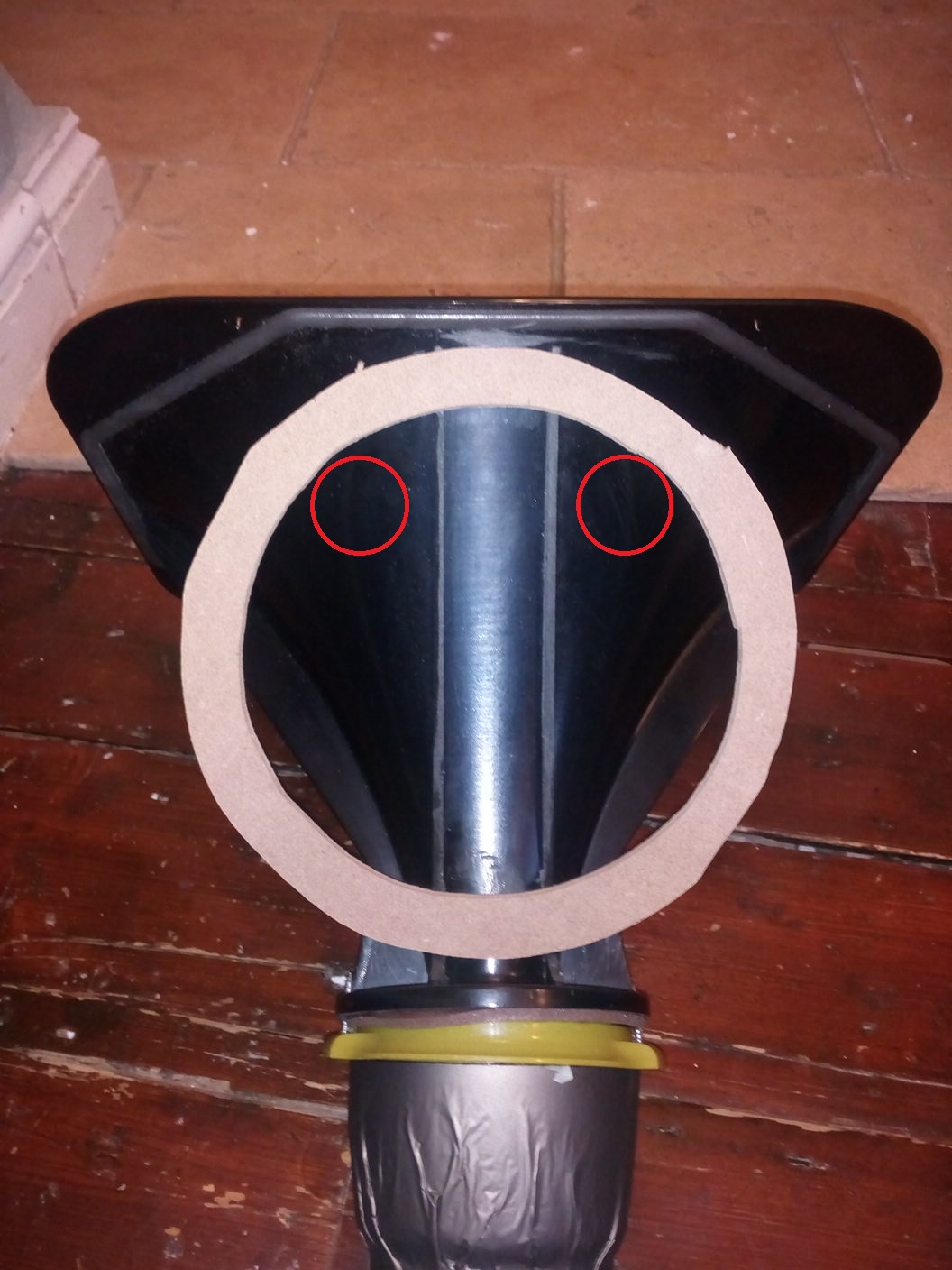
I looked up the method that X mentioned about using foam. I have attached a diagram that shows it taken from a pdf on volvotreter's site http://volvotreter.de/downloads/Edgar-Midrange-Horn.pdf

The driver used for this was a dome that was mounted in a larger horn mouth with a hole being cut in the foam for the dome. I'm not sure this would work as well with a 2.5 in cone driver but the article is quite interesting and has a lot of graphs that show the results for different mouth sizes and treatments.
I have a couple of spare Aura NSW2-326 drivers that are slightly smaller with good xmax and power handling but the response does drop in the high frequencies. Would be kind of like a high efficiency constant directivity linkwitz pluto tweeter (so really nothing like a pluto at all).
Will the drooping HF response be a deal breaker for use in a horn like this?
I can buy a couple of these waveguides for a good price if I add them onto another order I will be making soon so I am very interested in how cutting the woofer holes goes
I looked up the method that X mentioned about using foam. I have attached a diagram that shows it taken from a pdf on volvotreter's site http://volvotreter.de/downloads/Edgar-Midrange-Horn.pdf
The driver used for this was a dome that was mounted in a larger horn mouth with a hole being cut in the foam for the dome. I'm not sure this would work as well with a 2.5 in cone driver but the article is quite interesting and has a lot of graphs that show the results for different mouth sizes and treatments.
I have a couple of spare Aura NSW2-326 drivers that are slightly smaller with good xmax and power handling but the response does drop in the high frequencies. Would be kind of like a high efficiency constant directivity linkwitz pluto tweeter (so really nothing like a pluto at all).
Will the drooping HF response be a deal breaker for use in a horn like this?
Last edited:
Thanks for the drawing, but my idea is a bit different in that I want to seal the back end of the foam so that sound doesn't leak out of the space between the driver and horn flange, but for it to act as a 1/4-wave absorber stub to soften the hard discontinuity of the edge of the driver.
Yes, this is indeed a fast moving thread - and that is what happens when you put Bushmeister (who is an amazingly motivated, meticulous, and skilled experimenter/builder) and me, the one-foam-core-speaker-a-month build addict, you have a recipe for something happening in a hurry.
I think based on my simulations so far, either qnty 4 x 65mm dia holes located 10 cm back from the mouth (axial distance) or qnty 4 x equivalent CSA slots, arcs, whatever... It should work but the trick is getting the holes to also line up with the driver diaphragm extent.
This is the latest plan from Bushmeister posted earlier (you can replace those holes with slots, etc.) and it's up to you how big to make them - as small as 40mm and up to 65mm dia depending on your tolerance for chuffing:
Last edited:
What do you guys think of the Faital Pro LTH142 (60 deg x 50 deg) tractrix elliptical horn with 1.4in throat? It appears to be very close in size to the 18sound Xt1640.
350mm x 240mm mouth x 233mm deep. These are $60 ea in the US and I can get free shipping if I buy two.
http://www.parts-express.com/pedocs/specs/294-1042-faitalpro-lth142-4-bolt-specifications.pdf
This horn when mounted with the HF146 compression driver has a very response. $251 for the HF146 though. You could bass inject and do a XO at circa 500Hz but not sure how good compression driver's HD figures look at 500Hz.
http://www.parts-express.com/pedocs/specs/294-1023-faitalpro-hf146-8-specifications.pdf
Last edited:
Both are very similar but XT1464 has more constant directivity LTH142 beams more at high frequencies due to the tractrix shape.
Directivity indexes
XR1464 pretty flat between 2k and 6k with a rise and fall either end

LTH142 rising directivity with frequency but still very good

Both look well made and smooth and are more similar than different probably comes down to price and availability
Directivity indexes
XR1464 pretty flat between 2k and 6k with a rise and fall either end
LTH142 rising directivity with frequency but still very good
Both look well made and smooth and are more similar than different probably comes down to price and availability
Hmm I hadn't thought of it like that. Maybe that is why Faital's graphs of Horn and driver look so flat because the directivity of the horn is propping up the high end of the larger tweeters where it would likely drop off without it.
One of the attractions to me of the synergy/unity concept was that the on and off axis sound should be very similar which is why I was looking at conical or more constant directivity horns. Your tractrix foam core works well so maybe it doesn't matter too much.
The crossover on the faital compression drivers is 900Hz for full power and derated to lower power at 500Hz so it probably depends on the volume level expected as to how well they would perform.
X I edited my post before so you may not have seen it. As you have tried a few drivers in this configuration how do you think the Aura NSW2 would work?
One of the attractions to me of the synergy/unity concept was that the on and off axis sound should be very similar which is why I was looking at conical or more constant directivity horns. Your tractrix foam core works well so maybe it doesn't matter too much.
You could bass inject and do a XO at circa 500Hz but not sure how good compression driver's HD figures look at 500Hz.
The crossover on the faital compression drivers is 900Hz for full power and derated to lower power at 500Hz so it probably depends on the volume level expected as to how well they would perform.
X I edited my post before so you may not have seen it. As you have tried a few drivers in this configuration how do you think the Aura NSW2 would work?
I have a couple of spare Aura NSW2-326 drivers that are slightly smaller with good xmax and power handling but the response does drop in the high frequencies. Would be kind of like a high efficiency constant directivity linkwitz pluto tweeter (so really nothing like a pluto at all).
Will the drooping HF response be a deal breaker for use in a horn like this?
So does a phase plot like this mean my uTrynergy is working well phase wise up to 8kHz over a 45 deg half angle? Greater than 45 deg and it falls apart, and greater than 8kHz it falls apart coherency wise?
This is the corresponding gated frequency response:
I don't quite understand the gating you've applied next to the frequency dependant windowing. I wouldn't do that. If we take a gating of 5 ms, that would mean a gating where 4 cycles at 800 Hz still fit. An 1/6 octave frequency dependant window is 4.3 cycles long. So in my opinion it shoud be enough to only use that 1/6 octave frequency dependant window. No separate gating.
I'll tell you what I would do, I'd start up DRC-FIR (oh no, sorry
).I'd take the listening axis plot of your preference. I wouldn't pick on axis, probably 10 or 15 degree off axis.
Take that measurement, do like Greg did on the convolution thread: export the IR while putting a check mark at minimum phase. (export the minimum phase IR) You'd probably have to generate minimum phase first to do that.
Import that IR back into REW. Now apply the frequency dependant window to that plot. Look at phase and FR where the dip is in that plot. Maybe even run the Auto EQ from REW to see what REW would advise running it's analysis.
That way you'd correct for minimum phase deviations. This is the plot I would use, including the frequency dependant windowing, to base my EQ decisions on. Makes sense?
One more tip: also look at how these plots look gated with only one cycle FDW. Is the dip there at that point? Turn up the number of cycles from there, just to see what it does over time. Is it turning into a huge null at any point?
Last edited:
Or, I made these a few builds later - could go posh and use wood. Might be nice to have them showing if I go for dipole bass alignment with an open back.....
I have a plan!
I made these many moons ago......the 3 litre bowls would be just about perfect.....lined with dynamat and stuffed with fiberglass.
Loving the spherical back chamber ideas. I have a couple of the 8" bamboo blanda bowls for my MA alpair 5 and TB W3 just waiting to do the cutting work all finished otherwise. Mmm I love yacht varnish
How about this for an idea...
Make a interlocking grid of foam core/light ply (think pigeon holes for mail) and make it fit the rear hemisphere. Fill pigeon hole voids with foam /baf/wool.fibre.
The differing depths and contained absorbent should deal with any refections and deaden the sphere quite well - yes I have done this (audibly it works well, yet to measure it)
FWIW I take the SB65 everytime (by x polls I don't rate the faital drivers I have heard)
Hmm I hadn't thought of it like that. Maybe that is why Faital's graphs of Horn and driver look so flat because the directivity of the horn is propping up the high end of the larger tweeters where it would likely drop off without it.
One of the attractions to me of the synergy/unity concept was that the on and off axis sound should be very similar which is why I was looking at conical or more constant directivity horns. Your tractrix foam core works well so maybe it doesn't matter too much.
The crossover on the faital compression drivers is 900Hz for full power and derated to lower power at 500Hz so it probably depends on the volume level expected as to how well they would perform.
X I edited my post before so you may not have seen it. As you have tried a few drivers in this configuration how do you think the Aura NSW2 would work?
I just had a look at the NSW2 driver and it's interesting from a lot of aspects considering how compact it is.
http://www.parts-express.com/pedocs/specs/296-252_AuraSound_NSW2-326-8A_Specifications.pdf
But the 16dB fall from 10kHz to 20kHz is not good for matching with falling response in a horn. Sensitivity of 84dB is ok as well 5mm of xmax! You could try it but maybe as mids for mid injection near a central HF dome tweeter at the apex. Use with a 1in throat WG. The nice thing with the little Aura's is that they are so small and can allow mounting really close to the throat for a higher XO point.
Qnty 4 in series parallel would be 90dB add 10dB WG gain and it's a 100dB mid. Add 90dB dome tweeter and 10dB gain and you have balanced 100dB sensitive system. I would have to model it to see how low it can go but probably circa 500Hz. So maybe have Auras handle 500Hz to 2.5kHz and dome tweeter above that. Could even use the 1in throat ABS waveguide suggested earlier by another member.
But handling the 80Hz to 500Hz with 100dB sensitivity will take a pair of 12in pro sound 99dB woofers to get over a 5dB baffle step loss. How to fit that on? Maybe just WWgW on baffle?
Last edited:
Mondo,
I think you are suggesting an aperiodic vented rear chamber ? With current design Bushmeister is making the woofers need to be isolated from the SB65 or all that pressure will cause distortion by pushing the cone around. Unless the SB65 rear aperiodic chamber was vented outside.
But to make an aperiodic rear chamber doesn't require a bowl with vented and stuffed holes. A simple short Dagger TL maybe 10:1 with lots of stuffing and foam placed across exit terminus can do same thing. I have measured its ability to flatten an impedance peak. The sealed one with the wool roll and lots of stuffing can also achieve very good impedance flattening. Knowing how much rigor Bushmeister puts into his builds we can expect an impedance sweep of the SB65 in the Tupperware bowl I am sure of it.
ing grid of foam core/light ply (think pigeon holes for mail) and make it fit the rear hemisphere. Fill pigeon hole voids with foam /baf/wool.fibre.
The differing depths and contained absorbent should deal with any refections and deaden the sphere quite well - yes I have done this (audibly it works well, yet to measure it)
I think you are suggesting an aperiodic vented rear chamber ? With current design Bushmeister is making the woofers need to be isolated from the SB65 or all that pressure will cause distortion by pushing the cone around. Unless the SB65 rear aperiodic chamber was vented outside.
But to make an aperiodic rear chamber doesn't require a bowl with vented and stuffed holes. A simple short Dagger TL maybe 10:1 with lots of stuffing and foam placed across exit terminus can do same thing. I have measured its ability to flatten an impedance peak. The sealed one with the wool roll and lots of stuffing can also achieve very good impedance flattening. Knowing how much rigor Bushmeister puts into his builds we can expect an impedance sweep of the SB65 in the Tupperware bowl I am sure of it.
I don't quite understand the gating you've applied next to the frequency dependant windowing. I wouldn't do that. If we take a gating of 5 ms, that would mean a gating where 4 cycles at 800 Hz still fit. An 1/6 octave frequency dependant window is 4.3 cycles long. So in my opinion it shoud be enough to only use that 1/6 octave frequency dependant window. No separate gating.
I'll tell you what I would do, I'd start up DRC-FIR (oh no, sorry
I'd take the listening axis plot of your preference. I wouldn't pick on axis, probably 10 or 15 degree off axis.
Take that measurement, do like Greg did on the convolution thread: export the IR while putting a check mark at minimum phase. (export the minimum phase IR) You'd probably have to generate minimum phase first to do that.
Import that IR back into REW. Now apply the frequency dependant window to that plot. Look at phase and FR where the dip is in that plot. Maybe even run the Auto EQ from REW to see what REW would advise running it's analysis.
That way you'd correct for minimum phase deviations. This is the plot I would use, including the frequency dependant windowing, to base my EQ decisions on. Makes sense?
One more tip: also look at how these plots look gated with only one cycle FDW. Is the dip there at that point? Turn up the number of cycles from there, just to see what it does over time. Is it turning into a huge null at any point?
On second thought, rather than posting the reply to this over in the Trynergy thread, I will keep it here because I think this can be useful to Bushmeister in figuring out how to best EQ the native SB65 in waveguide response.
As I cannot take new data, I am playing around with the data I have already and doing what you suggest:
1. Generate minimum phase data
2. Export IR as wav file
3. Close existing data and import IR wav file
4. Apply FDW from 1 cycle to 6 cycles and look at FR behavior and phase behavior
5. Use curves generated from this process to base EQ decisions with the goal to flatten the minimum phase with gentle adjustments in 6 cycle space
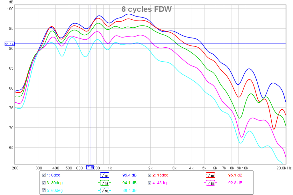
So here is the Frequency Response from the re-imported min phase IR for 6 cycle FDW (ignore the blue cursor - I accidentally checked the show cursor box and its on random location):
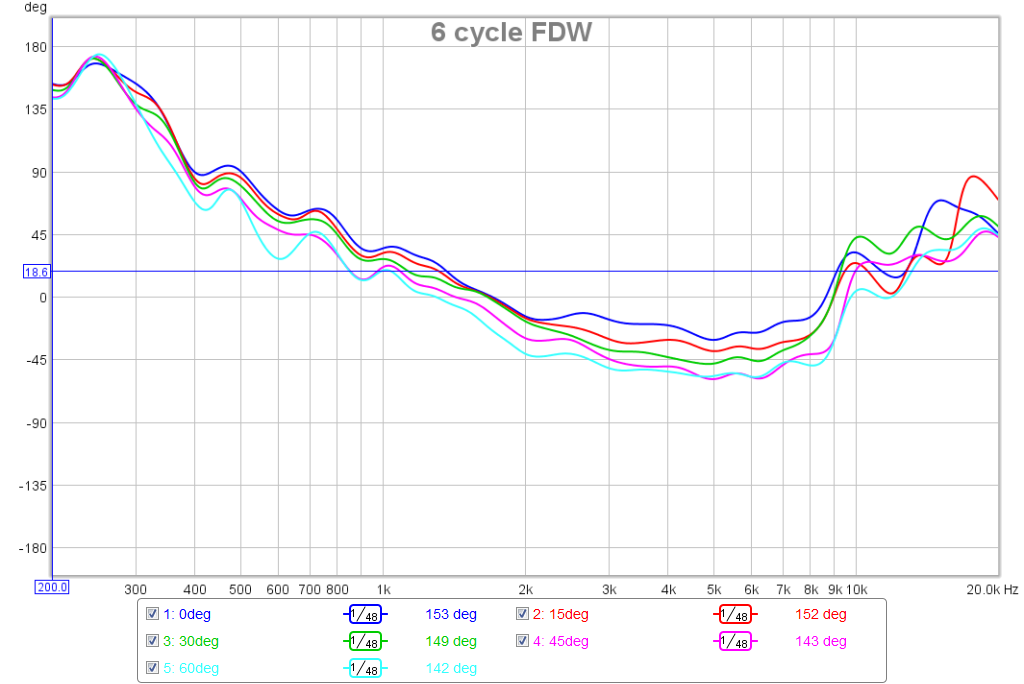
Phase for 6 cycle:
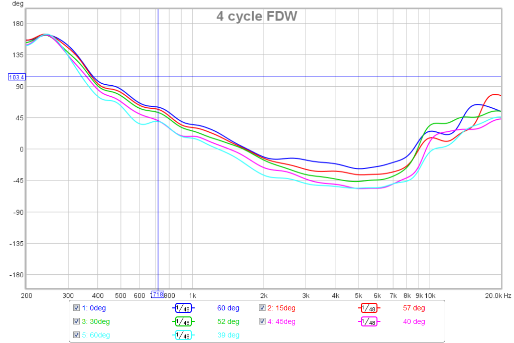
Freq for 4 cycles:

Phase for 4 cycles:
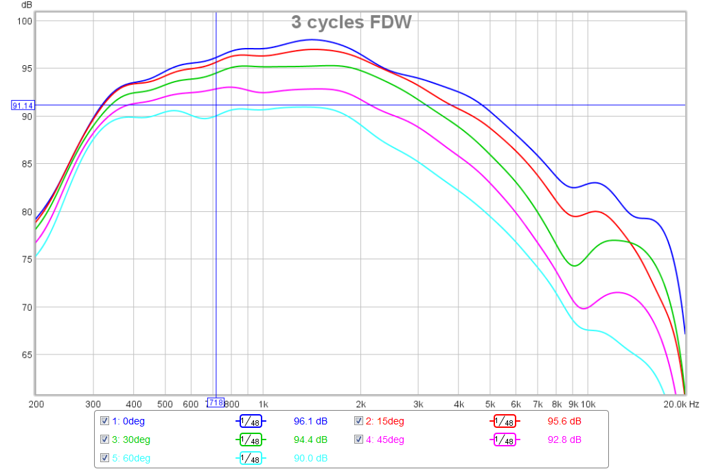
Freq for 3 cycles:
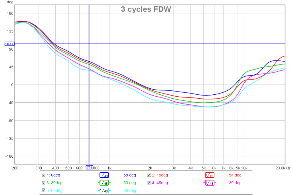
Phase for 3 cycles:
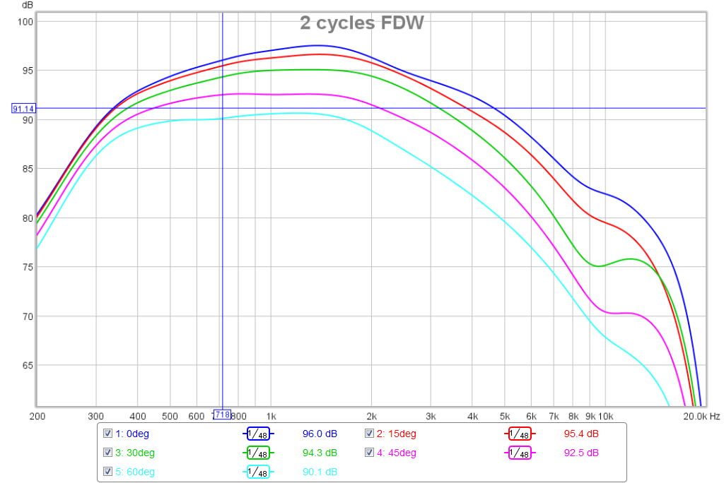
Freq for 2 cycles:
Phase for 2 cycles:

Freq for 1 cycle:

Phase for 1 cycle:
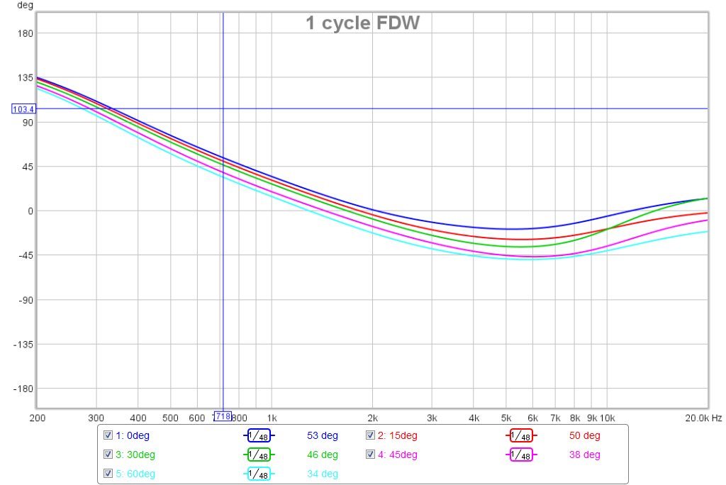
Based on the above analysis, it appears that the dip starts to show up in earnest at 3 cycles and the minimum phase is pretty consistent here. It would seem that to first order, an EQ to flatten the 3 cycle FDW would be a good gentle touch to get the system to go in the right direction to correct and help flatten the minimum phase, which you are proposing as the goal to shoot for best sound quality.
This is really helpful because it helps to separate what is correctable from the intrinsic behavior of the driver in WG vs what is really uncorrectable (without room treatments/positioning).
Attachments
-
 Freq-2-cycles-FDW.png97.6 KB · Views: 705
 -
 Phase-2-cycles-FDW.png83.6 KB · Views: 696
 -
 Freq-1-cycles-FDW.png94.6 KB · Views: 708
 -
 Phase-1-cycles-FDW.png79.4 KB · Views: 708
 -
 Phase-3-cycles-FDW.png83.5 KB · Views: 703
 -
 Freq-3-cycles-FDW.png98.8 KB · Views: 708
 -
 Phase-4-cycles-FDW.png83.1 KB · Views: 699
 -
 Freq-4-cycles-FDW.png100.2 KB · Views: 730
 -
 Phase-6-cycles-FDW.png87.4 KB · Views: 737
 -
 Freq-6-cycles-FDW.png110 KB · Views: 740
Last edited:
3 cycle FDW - REW auto EQ process
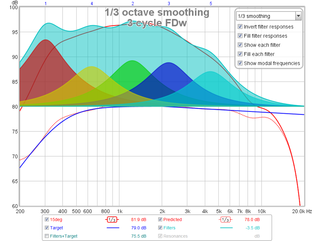
So I tried the auto EQ in REW, and in fact, this feature is the software's namesake (Room EQ Wizard) which I have never used before. I know there is going to be some play here as the outcome is very dependent on the input settings you give it. Here is my first try at it and I am using the 3 cycle FDW minimum phase data at 15 deg as the basis for my horn EQ.
Here is a snapshot of the settings and the resulting auto EQ "sand painting chart" that resulted. (looks like a native American sand painting):
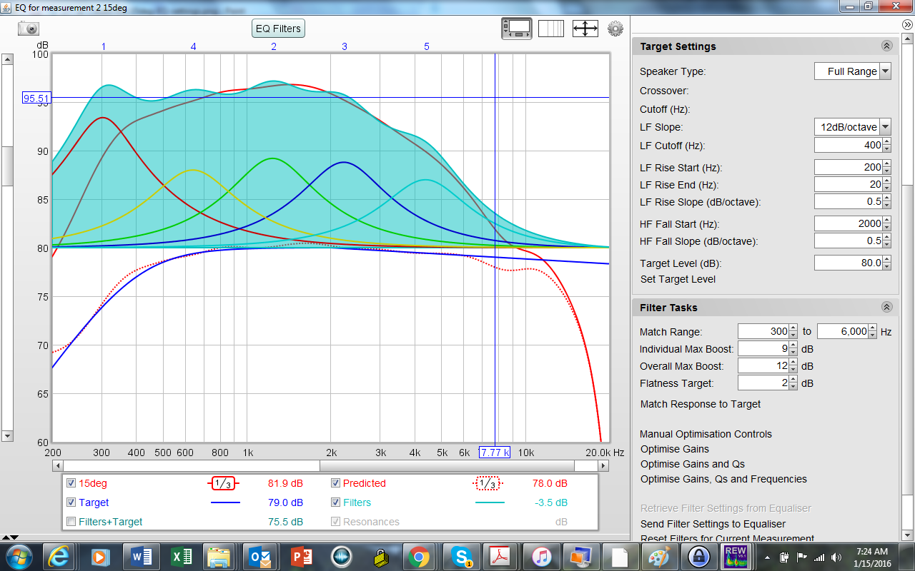
Here is a closeup of the EQ filters that were applied along with the target (blue line) and the predicted outcome (dashed red line), note that filter responses have been inverted for clarity:
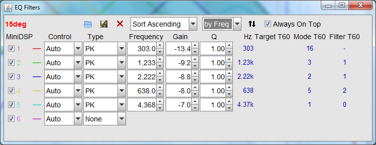
Here are the suggested miniDSP PEQ's settings:
The predicted target still has the dip which I decided to leave alone by setting the target match below 6kHz. The HF falloff can be dealt with using a manually applied high shelf separately.
I think the predicted curve looks pretty good and it will be interesting to see how the measured minimum phase works out - probably flattened quite a bit.
I think this is all starting to make a lot more sense now. Am I on the right track?
Thanks Wesayso.
So I tried the auto EQ in REW, and in fact, this feature is the software's namesake (Room EQ Wizard) which I have never used before. I know there is going to be some play here as the outcome is very dependent on the input settings you give it. Here is my first try at it and I am using the 3 cycle FDW minimum phase data at 15 deg as the basis for my horn EQ.
Here is a snapshot of the settings and the resulting auto EQ "sand painting chart" that resulted. (looks like a native American sand painting):
Here is a closeup of the EQ filters that were applied along with the target (blue line) and the predicted outcome (dashed red line), note that filter responses have been inverted for clarity:
Here are the suggested miniDSP PEQ's settings:
The predicted target still has the dip which I decided to leave alone by setting the target match below 6kHz. The HF falloff can be dealt with using a manually applied high shelf separately.
I think the predicted curve looks pretty good and it will be interesting to see how the measured minimum phase works out - probably flattened quite a bit.
I think this is all starting to make a lot more sense now. Am I on the right track?
Thanks Wesayso.
Attachments


Last edited:
- Home
- Loudspeakers
- Multi-Way
- A Bookshelf Multi-Way Point-Source Horn