Alright, I have been looking to source class-D modules that would comfortably, and reliably I might add, drive a 2-Ohm load up to 500-800W.
There's several modules that would do that, the Hypex UcD2K for example, so I bought a couple and evaluated them. And although nice, the complexity and size/cost have turned me away from them. I hear plenty of reports of the SMPS that goes with them failing and the idle dissipation is a tad high in my opinion.
So I started looking at alternatives and found a couple of suitable modules based on the popular IRS2092. Unfortunately after receiving a number of these, either sourced through eBay or from Chinese suppliers, the quality and performance just isn't up to the standard I'd like to stick to.
They work, but there's all sorts of issues associated with them. These issues could probably be fixed with some tweaks and modifications. But once I get started with that I might as well start from scratch as the IRS2092 is pretty well documented. Since I already have these modules they can now be used to compare and evaluate design choices.
So you guessed it, I'll be rolling my own. However in order to avoid not documented pitfalls or issues I was hoping to get some tips and suggestions on implementing the IRS2092? Any do's and don'ts I need to be aware of? Anything that isn't covered in the datasheet and application notes that is worth considering? Etc.
I would welcome and appreciate feedback that'll help me with getting a schematic and PCB drafted quickly avoiding most of the known issues.
Best place to start would be to have a very good look over the various IRS2092 app notes, and the IRAUDAMP9 reference design. It is more power than you require, but designed around a 2 ohm load.
Best place to start would be to have a very good look over the various IRS2092 app notes, and the IRAUDAMP9 reference design. It is more power than you require, but designed around a 2 ohm load.
Thanks, that's indeed what I've been doing already. It probably wouldn't surprise you if I told you I've found quite a number of inconsistencies between the various IRAUDAMP PDFs, the app notes from IRF and the IRS2092 datasheet. I'll need to compile a list and figure out what's what exactly.
You might have a look at http://www.diyaudio.com/forums/class-d/255046-systemd-liteamp.html
Choco has some knowledge about the interna of IRS2092
Choco has some knowledge about the interna of IRS2092
I originally went the silly route and designed my own pcb and used IR datasheet and app notes. It didn't work very well at all, it would reset on medium to high volumes.
I had troubles with decoupling the 2092 and the mosfets.
PCB layout was poor too with long pcb tracks.
I had trouble with the VCC supply being noisy.
I also had a big problem on power down with large smoothing capacitors. On power off I would get a siren type noise then a massive thump through the speaker. IR suggested using a reset circuit that holds the 2092 in reset when VCC drops too low and that worked fine.
I did get a working layout after 3 tries and a bit of fiddling with over current detect circuits.
I think the best approach is to use the IRAUDAMP pcb and circuit IR give you as that works.
I was daft enough to try a power supply inductor for the 2092 output inductor.
It quickly reached 120 degrees c !
I found a good output inductor core is T106-2.
It quickly reached 120 degrees c !
I found a good output inductor core is T106-2.
Key for success with the IRS2092 and all of the modern IRS drivers is to get the PCB including snubbers right.
The protections of these IRS chips are good, but the HF resonances of a poor half bridge layout and/or inadequate snubbering can easily cause phantom tripping of the protections. This turns more and more difficult with increasing power.
500W-800W into 2R:
The largest MosFets which you can drive directly from the IRS2092 without additional drivers are the IRFB4227.
Their limit of reasonable operation is about 500W into 4R with +/-70V rails.
500W-800W into 2R:
The largest MosFets which you can drive directly from the IRS2092 without additional drivers are the IRFB4227.
Their limit of reasonable operation is about 500W into 4R with +/-70V rails.
I found I needed gate drivers for 4227's.
If I didn't they switched on too slowly and reset the 2092 on medium to high power.
I could only get 4019 mosfets to work with 2092 on its own.
Well, the IRFB4227 is almost factor two more heavy than recommended for the IRS2092. Nevertheless it is possible, however there are plenty of reasons why one or the other implementation might not work properly. Finding the root cause needs very detail examination of the switching events at various load situations.
In my experiments the IRS2092 behaved surprisingly well, when driving the IRFB4227. Gate drive signal quality was acceptable.
Using the values as decribed below, the temperature of the IRS2092 settled at roughly 70C, with an ambient of 25C.
Gate drive resistor 6R8 and in parallel a shottky diode for turning off.
(Using a PNP instead of the diode would be even more fortunate).
Dead time setting: 75ns.
Use 11V-12V supply voltage for the internal gate drivers of the IRS, not 15V!
Keep the switching frequency below 280kHz.
This is fine for rail voltages of +/-70V and 4R load.
Trials with +/-82V and 4R were also working without defects on the bench and delivered up to 600W, but detail examination of MosFet losses and SOA clearly showed that for this construction and 4R load any rails above +/-70V are not promising in terms reliablity. And even this is already questionable for PA use. Behringer does a similar thing, but they spend some additional external diodes (in parallel to the body diodes) in order to milden the reverse recovery headache and have implemented a thermal back regulation.
I didn't go as low as 6r8 gate resistors so that's probably why mosfet didn't switch on fast enough.
I used 10R gate resistors with npn/pnp buffers into 2 pairs of 4227.
I used 10R gate resistors with npn/pnp buffers into 2 pairs of 4227.
Last edited:
D
Deleted member 148505
Well, the IRFB4227 is almost factor two more heavy than recommended for the IRS2092. Nevertheless it is possible, however there are plenty of reasons why one or the other implementation might not work properly. Finding the root cause needs very detail examination of the switching events at various load situations.
In my experiments the IRS2092 behaved surprisingly well, when driving the IRFB4227. Gate drive signal quality was acceptable.
Using the values as decribed below, the temperature of the IRS2092 settled at roughly 70C, with an ambient of 25C.
Gate drive resistor 6R8 and in parallel a shottky diode for turning off.
(Using a PNP instead of the diode would be even more fortunate).
Dead time setting: 75ns.
Use 11V-12V supply voltage for the internal gate drivers of the IRS, not 15V!
Keep the switching frequency below 280kHz.
This is fine for rail voltages of +/-70V and 4R load.
Trials with +/-82V and 4R were also working without defects on the bench and delivered up to 600W, but detail examination of MosFet losses and SOA clearly showed that for this construction and 4R load any rails above +/-70V are not promising in terms reliablity. And even this is already questionable for PA use. Behringer does a similar thing, but they spend some additional external diodes (in parallel to the body diodes) in order to milden the reverse recovery headache and have implemented a thermal back regulation.
Got exactly the same result with the temperature of IRS2092.
I am using DIP version of IRS2092 driving IRFB4227 directly.
Voltage rails +/-87VDC.
Gate resistors are 4.7R.
250kHz is good without buffer for IRFB4227, if you go lower, the inductor temperature will rise.
Because of high temperature of IRS2092, and inductor heating when using IRFB4227, I cannot suggest it. I'm getting 10W power consumption at idle.
Just use IRFB4615. IRS2092 DIP can drive it with ease. You can achieve 500W @ 2ohms with +/-60VDC rails, just provide good heatsinking for output mosfets.
If you really want the IRFB4227 use totem pole buffer.
For 1 pair IRFB4227, use transistors with low Vce Saturation Voltage, DC Collector Current of 2A or higher and dissipation of 1W or higher.
http://www.nxp.com/documents/data_sheet/PBSS5350T.pdf
http://www.nxp.com/documents/data_sheet/PBSS4350T.pdf
http://www.nxp.com/documents/data_sheet/PBSS4041NT.pdf
http://www.nxp.com/documents/data_sheet/PBSS4041PT.pdf
Run it at 500khz and the inductor will be at room temperature on idle. 🙂
Do not use IRS2092S SMD ic, there are lot of fakes out there and will blow up at +/-80VDC. Use AUIRS2092S from reputable electronics store if you're planning SMD+buffer.
Attachments
Last edited by a moderator:
Thanks everyone, that's most helpful, I'm in the process of drafting a schematic and will update this topic as soon as it is somewhat presentable.
Just use IRFB4615. IRS2092 DIP can drive it with ease. You can achieve 500W @ 2ohms with +/-60VDC rails, just provide good heatsinking for output mosfets.
...yup, had forgotten the nice 4615 !
Confirming your results. I used them not with the IRS2092, but with IRS20957 and found them touching their limits for 2R at +/-60V rails when running at roughly 400kHz switching frequency. So with 250...300kHz they should be fine with 2R and +/-60V.
D
Deleted member 148505
Use 11V-12V supply voltage for the internal gate drivers of the IRS, not 15V!
Hi Markus,
I overlooked this important detail, I reduced VCC to 11.7 volts and now the IRS2092 chip is now significantly cooler 🙂
Thanks!
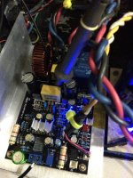
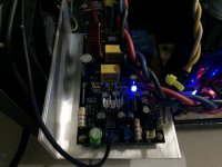
With my current setup I'm getting 1KW @ 2ohms dummy resistor (5 seconds) +/-85V DC
Though I don't like any heat specially on IRS2092. Not suitable for active speaker systems.
Attachments
The driver heat grows almost with the square of the driver supply voltage.
Detailed measurements and analysis of worst case switching losses and calculation of die temperature would tell you that you are brave man. 🙂
Please keep us tuned about your reliability experiences of this set up.
4227 is a tough one, nevertheless a single pair of 4227 will have a life on the edge with this and survive just because fs drops towards larger signals.Hi Markus,
With my current set up I'm getting 1KW @ 2ohms dummy resistor (5 seconds) +/-85V DC
Detailed measurements and analysis of worst case switching losses and calculation of die temperature would tell you that you are brave man. 🙂
Please keep us tuned about your reliability experiences of this set up.
Something I have learned with time is that a minimum degree of complexity is required in order to produce universal designs, those ones that can be successively used as building (or teaching) blocks (because they suit practical needs matched to the world), while allowing to permanently unload from the brain most of their related complexity. Something like "dealing with some more complexity now to allow dealing with less complexity later".
Good class-D requires a minimum degree of complexity. Any reference design of any appliance requires a minimum degree of complexity. Cost optimization must be something implicit in a "reference design" (here I use the concept in the professional industry sense, not in the high end audio sense), and it is not only production cost optimization, it is life expectancy, and potential repair or refurbishment costs.
For example, IRS20957 or IR2092 chips can drive FET gates directly, but this results in sub-optimal gate waveforms when trying to get the best dead time and switching performance, and when one FET fails the IC almost always becomes toasted too. When gate resistor value is low most heat goes to the IC (for example, internal gate ON resistance of IRS20957 is like 10 ohm). Adding buffer NPN/PNP changes this, better control of dead time and switching performance, heat shared (between IC, buffers, and gate resistors) and when the NPN/PNP are rugged enough they survive FET fail conditions, at worst only gate resistor blows, this allows easier repair, more DIY friendly, structural strength.
Then the problem becomes increased part count. Dual, triple and quad parts are the solution. This requires a good deal of creativity to develop circuit topologies that make good use of these parts, but the result is higher "circuit functional value" at reduced part count. For example, the NPN/PNP gate drive buffers can come in a single package. This is, of course, SMD. There is a growing selection of dual, triple and quad SMD parts available. I don't think all-through-hole is suitable for class D.
When the designs have not enough complexity the result is going to be always like the Chinese stuff from ebay. A good class D schematic is never going to look as straight-forward as a good class AB schematic.
Last edited:
Something I have learned with time is that a minimum degree of complexity is required in order to produce universal designs, those ones that can be successively used as building (or teaching) blocks (because they suit practical needs matched to the world), while allowing to permanently unload from the brain most of their related complexity. Something like "dealing with some more complexity now to allow dealing with less complexity later".
Good class-D requires a minimum degree of complexity. Any reference design of any appliance requires a minimum degree of complexity. Cost optimization must be something implicit in a "reference design" (here I use the concept in the professional industry sense, not in the high end audio sense), and it is not only production cost optimization, it is life expectancy, and potential repair or refurbishment costs.
For example, IRS20957 or IR2092 chips can drive FET gates directly, but this results in sub-optimal gate waveforms when trying to get the best dead time and switching performance, and when one FET fails the IC almost always becomes toasted too. When gate resistor value is low most heat goes to the IC (for example, internal gate ON resistance of IRS20957 is like 10 ohm). Adding buffer NPN/PNP changes this, better control of dead time and switching performance, heat shared (between IC, buffers, and gate resistors) and when the NPN/PNP are rugged enough they survive FET fail conditions, at worst only gate resistor blows, this allows easier repair, more DIY friendly, structural strength.
Then the problem becomes increased part count. Dual, triple and quad parts are the solution. This requires a good deal of creativity to develop circuit topologies that make good use of these parts, but the result is higher "circuit functional value" at reduced part count. For example, the NPN/PNP gate drive buffers can come in a single package. This is, of course, SMD. There is a growing selection of dual, triple and quad SMD parts available. I don't think all-through-hole is suitable for class D.
When the designs have not enough complexity the result is going to be always like the Chinese stuff from ebay. A good class D schematic is never going to look as straight-forward as a good class AB schematic.
Nice to see you back again here!🙂
@Eva,
I've been wondering whether additional gate drivers would provide helpful not only with driving MOSFETs with a higher gate capacitance (such as the IRFB4227) but also to reduce heat buildup in the IRS2092 and provide cleaner switching and better slewrate on the output (Ton/Toff). This would also go towards reducing EMI and lowering THD if my logic does not err me.
The defacto solution would be to use a totem pole configuration, which although simple, has its own set of issues as the output does not necessarily track the input with accuracy and the Ton/Toff is not exactly specified or symmetrical and a function of transistor parameters.
Hence I've been looking for MOSFET gate drivers with plenty of gate drive capability and identical Ton/Toff switching, the following gate driver ICs seem to fit the bill and would be trivial to put on the PCB:
ZXGD3002E6TA
http://www.diodes.com/_files/datasheets/ZXGD3002E6.pdf
MIC4420YMM/TC4420
http://www.micrel.com/_PDF/mic4420.pdf
Am I chasing a read herring here, or has this approach merit?
@Choco,
I read through your 'SystemD LiteAmp' topic which proved to be an excellent read although one of the things that did stick out like a sore thumb is your comments on the noise contribution of the OTA in the IRS2092 to the S/N ratio of the whole amplifier. I remember designing and building a UcD style amplifier back in 2005 (yes, we're getting old indeed!) with the TDA8939, which I ultimately scrapped due to the built in comparator being rather noisy, I'd rather avoid a repeat exercise.
Would selecting the IRS20957 rather than the IRS2092 be a better choice here in terms of amplifier S/N ratio? It would obviously require a larger number of parts to construct the amplifer, as the OTA has now got to be built up externally, either using discrete parts or ICs.
@Eva,
I've been wondering whether additional gate drivers would provide helpful not only with driving MOSFETs with a higher gate capacitance (such as the IRFB4227) but also to reduce heat buildup in the IRS2092.
I found the 2092 gets warm even with npn/pnp gate drivers.
- Status
- Not open for further replies.
- Home
- Amplifiers
- Class D
- Tips and suggestions on IRS2092 implementation?