@Dimonis,
Thanks! There seems to be a discrepancy between the various datasheets and application notes in terms of the dead-time settings, but I'll take your word for it that with the IRFB4615 I selected the DT3 dead-time setting is the most suitable.
Thanks! There seems to be a discrepancy between the various datasheets and application notes in terms of the dead-time settings, but I'll take your word for it that with the IRFB4615 I selected the DT3 dead-time setting is the most suitable.
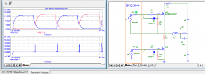
You can see in the simulator that at 15Ohm in gate we have a shootthrough 😉
It's an easy way to check any mosfets......
It's an easy way to check any mosfets......
Attachments
Last edited:
@Dimonis,
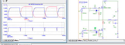
I initially had the 10K resistor from the gate to the source in my schematic as well, however I was told it does not make any difference. Could you perhaps rerun your simulation without it? Also, it would be interesting to see the effect of the diode across the dead-time resistor.
I initially had the 10K resistor from the gate to the source in my schematic as well, however I was told it does not make any difference. Could you perhaps rerun your simulation without it? Also, it would be interesting to see the effect of the diode across the dead-time resistor.


From IR library.
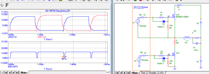
It's theoretical reasoning and here is my practical :
http://www.powersmps.ru//CDA2092-2/index.html
PS Don't make the bias supply more than 12V
It's theoretical reasoning and here is my practical :
http://www.powersmps.ru//CDA2092-2/index.html
PS Don't make the bias supply more than 12V
Last edited:
2092 cannot work with post-fiter feedback , several years ago I tryed making a UcD-type of it - too many issues - not worth it ....
If you need UcD , just take IRS20957+LM311
If you need UcD , just take IRS20957+LM311
Interesting topic.
Glad some guys joined in, because it creates a lot of interesting discussions and inside looks.
Overall, the whole design and approach looks very similar to something I developed a couple of years ago. Total board dimensions were 50x100mm and one of the main goals was ease of mounting/production.
I only had some weird DC offset, at the end it all had to do with some interaction between overall gain, dead-time and gate resistors before the gate buffers.
Anyone any idea about that?
I need to cut some details in the design, but I don't mind sharing it under OSHW license if people find it interesting to take it to even an higher level.
Last edited:
- Status
- Not open for further replies.
- Home
- Amplifiers
- Class D
- Tips and suggestions on IRS2092 implementation?