I remember one firm I worked for after a stock check we were down over 1 million 0.1uf 0603 Caps (decoupling), and that was only with 3 lines running 24/7... The rep who sold us most of the components had a nice Jag and a big house!!!!! And on another job a connector manufacturer had to build an extra line just to supply the connectors we needed... Not quite up there with Hon Hai Precision Industry though🙂
Whilst we are on this here's a bit of info on some thermally conductive laminates that may be of interest to some as I am playing with automotive light modules (that save power, but have a big resistor to waste heat so the ECU knows the lights are there!!!!!... (also I have another record of the links...🙂
http://www.cofan-pcb.com/download/material/92ML.pdf
LAMAR - Products: Laminates & Prepregs: Thermally Conductive
Guidelines for Thermal Management Products - VT-44A
http://www.cofan-pcb.com/download/material/92ML.pdf
LAMAR - Products: Laminates & Prepregs: Thermally Conductive
Guidelines for Thermal Management Products - VT-44A
Marce, Bonsai,
It does seem appropriate these days to use surface mount device wherever you can even if it is just for size reduction. Of course it is going to be more difficult to do a diy project with these parts even if you can do it. It is going to take different skills and equipment to do it, but that can be learned and will happen.
The question is how to combine these small parts with the larger thru hole output power devices needed in a power amp? Will manufacturers really kill the output transistors that are preferred by the diy and smaller audio companies? Will we all be forced to go the class D route by fiat, will the requirements for power consumption make it impossible for the small manufacturer to produce an amp with a large BJT or mosfet output device. Bonsai, you have just retired, but Marce you are still involved actively in board design so I imagine you are having to keep up with new requirements placed on the industry by governmental rules and things like CE or UL or whoever makes the rules that true manufacturers have to follow. Are we looking at another ten years of these larger devices or is the hammer coming down sooner than that? Will all of our power amps fit in the palm of our hands in a few more years or are there enough other reasons or applications that will keep these larger thru hole devices around for other reasons that the fear of losing them is really overblown?
answer that
A flir cam thermal image is easy enough to take of an opened metal can in-situ. Looking at the Rjc and Rja numbers of e.g. an LM4562, I'd guess that a thermal image of the die could be more than a blur.
Resolution of digitalised xray imaging nowadays is excellent, I remotely accessed files on the main frame of my g/f's hospital many times, and downloaded them for enhancing. Wouldn't even require removing the die out of a metal can, likely just shoot through the package of an SOIC.
Question is whether the latter would be necessary ?
I've seen plenty transistor dies of TO5/TO99 I guillotined, but never been eye-to-die of an IC. Maybe a regular digital cam picture would also suffice for an IC opamp die ?
(As an aside, still dying to hear which part of the UK you picked as your layer, my Liege)
Last edited:
Pretty pictures, x-rated mags start to bore me.
(I was aroused by the thought of correlating dissipation and current level on a 5000 mil² scale)
(I was aroused by the thought of correlating dissipation and current level on a 5000 mil² scale)
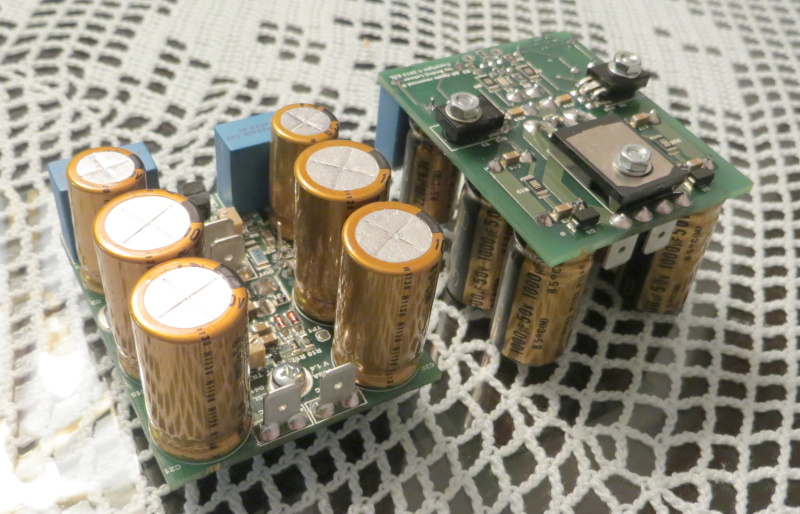
Have a look with the very elegant way Lazy Cat managed it on his VSSA and First one amplifiers.The question is how to combine these small parts with the larger thru hole output power devices needed in a power amp?
Power devices and Drivers (all the ones requiring a cooler) are soldered on the back side of the printed board (the tracks side). They are used as spacers to isolate the circuit from the radiator, and the through holes are used to screw the all circuit on the radiator. This minimizes the surface and further reduce the length of the paths.

Last edited:
Pretty pictures, x-rated mags start to bore me.
(I was aroused by the thought of correlating dissipation and current level on a 5000 mil² scale)
Just a different X, right? 🙂
https://www.chipworks.com/about-chipworks/overview/blog
Especially their older blogs have some really cool FIB/SEM imagery and die shots.
Thanks for the link.
(I bring the life-ly spice, but somewhat fatiguing and one-track minded)
(I bring the life-ly spice, but somewhat fatiguing and one-track minded)
Just a different X, right? 🙂
https://www.chipworks.com/about-chipworks/overview/blog
Especially their older blogs have some really cool FIB/SEM imagery and die shots.
Very cool site!
Yeah, Chipworks blog is great stuff. Loads to learn from it as well. Enjoy, guys. 🙂
Bummer--their stuff from late 200_ was much more thorough, doesn't seem to be on the site anymore.
Bummer--their stuff from late 200_ was much more thorough, doesn't seem to be on the site anymore.
Last edited:
A flir cam thermal image is easy enough to take of an opened metal can in-situ. Looking at the Rjc and Rja numbers of e.g. an LM4562, I'd guess that a thermal image of the die could be more than a blur.
This technique scales down to microns of resolution by painting it onto a die. The liquid crystal can be formulated for many temperature/color ranges but it's expensive.
https://www.youtube.com/watch?v=peewxRlNVqg
So am I, yet I had no problem understanding the point and finding the relevant information in the cited datasheet. Perhaps being uncredentialed is a virtue.
Hey SY, can I be uncredidentialed too? Go ahead, knight me....
Hey SY, can I be uncredidentialed too? Go ahead, knight me....
No doubt that some motivated, well informed, and talented amateurs can whip professional's @$$, regardless of profession.
Yes those nixie tubes, but a different circuit. After a 1/3 octave filter you don't need a true RMS detector. You can then do the log conversion with a comparator.
I wanted to know how well a 2 - CFA (LM7171) diff amp would work. I gathered my TH parts and plugged them in and started measuring the circuit.
I can put this together faster than SIM and almost as fast to change part values.
Q: How do I do breadboarding with SMD as fast as I can with TH parts?

THx-RNMarsh
I can put this together faster than SIM and almost as fast to change part values.
Q: How do I do breadboarding with SMD as fast as I can with TH parts?
THx-RNMarsh
Last edited:
you find/makeup a standard breadboard for common topology configurations and have a pcb fab it for you. sad but real.
cheers
Alan
cheers
Alan
I wanted to know how well a 2 - CFA (LM7171) diff amp would work. I gathered my TH parts and plugged them in and started measuring the circuit.
I can put this together faster than SIM and almost as fast to change part values.
Q: How do I do breadboarding with SMD as fast as I can with TH parts?
View attachment 523560
THx-RNMarsh
The HP6237B. A great near ubiquitous power supply.
- Status
- Not open for further replies.
- Home
- Member Areas
- The Lounge
- John Curl's Blowtorch preamplifier part II