Amp needed name.😀
Let's call it XLD 1.0 😉 I'm trying to use 3-letter abbreviations for my designs now 😀
Let's call it XLD 1.0 😉 I'm trying to use 3-letter abbreviations for my designs now 😀
OK. 🙂
I don't have any 18R resistors in stock for R17 and R18 on the output boards. Will I be able to correct the increased current flow of 15R resistors when doing bias adjustments?
One more implementation - for those, who likes symmetry 😉
Symmetric slew and clipping by design, rather high speed, very low distortion.
I made it DC-coupled. If someone wants to add a cap at the input - a good way to do it is to have 2 pairs of input RCA's (DC and AC coupled) and solder the cap right on their pins.
Worth testing.
Jeff, are you up to one more layout? 😉
I'm sure it can be kept within 3"x3" as well 🙂
Cheers,
Valery
P.S. Sorry. JPG schematic if difficult to read - PDF looks much better.
I make simulation of an amplifier with this topology. It can make very high slew rate and very low THD at low power. But near clipping THD is high but still acceptable. At low power, THD profile is almost "monotonic" 😎
At beginning, I have oscillation when clipping but now it solved.
Very good topology, thank you for sharing it here. I will make an implementation of my simulation soon.
I don't have any 18R resistors in stock for R17 and R18 on the output boards. Will I be able to correct the increased current flow of 15R resistors when doing bias adjustments?
Hi Jeff, 15R is going to be ok.
Please don't forget to use 150pF as C9, C10.
Hi Jeff, 15R is going to be ok.
Please don't forget to use 150pF as C9, C10.
Thanks. I'm missing a few other values of resistors as well, so I need to wait to finish this.😡
VERTICAL IPS + Non-switching OPS
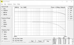
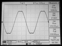
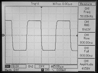
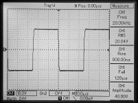
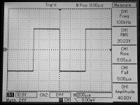
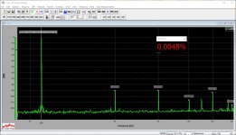
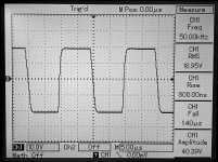
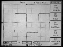
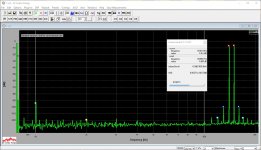
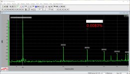
Tested and measured Vertical IPS (CFA) with non-switching OPS.
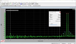
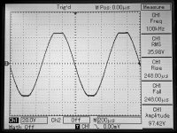
Spectrums are 50W @ 8 ohm, square waves are 40V p-p, clipping is close to the rails (100V p-p).
Measured slew rate is around 100V/uS. Not bad 😎
I will publish minor updates to the Vertical soon.
Tested and measured Vertical IPS (CFA) with non-switching OPS.
Spectrums are 50W @ 8 ohm, square waves are 40V p-p, clipping is close to the rails (100V p-p).
Measured slew rate is around 100V/uS. Not bad 😎
I will publish minor updates to the Vertical soon.
Attachments
-
 10-bode-1MHz.JPG68.9 KB · Views: 1,218
 -
 DSC_0135.JPG441.6 KB · Views: 225
 -
 DSC_0134.JPG433.6 KB · Views: 204
 -
 DSC_0133.JPG469.6 KB · Views: 196
 -
 DSC_0132.JPG483.5 KB · Views: 290
 -
 DSC_0130.JPG426.5 KB · Views: 311
 -
 11-imd-14-15khz.JPG190 KB · Views: 914
 -
 10-thd-020khz.JPG177.3 KB · Views: 982
 -
 10-thd-010khz.JPG176.1 KB · Views: 1,049
 -
 10-thd-001khz.JPG187.5 KB · Views: 1,169
Last edited:
Hi
had set up a thermal simulation , am confused..which transistor actually senses the heatsink temp?
Thanks
had set up a thermal simulation , am confused..which transistor actually senses the heatsink temp?
Thanks
Hi
had set up a thermal simulation , am confused..which transistor actually senses the heatsink temp?
Thanks
Hi, on the schematic in post #348:
http://www.diyaudio.com/forums/soli...e-old-ideas-1970s-ips-ops-35.html#post4554894
the one sensing for bias setting Is Q3.
Q4, Q5 are also on the heatsink, adjusting the clamping voltage.
VERTICAL IPS - final schematic
Removed the caps in parallel with R17, R18.
R19, R20 value is slightly increased to match the current settings of the non-switching OPS. Jeff - these values will be good for your "bundle".
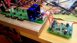
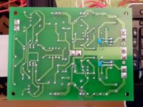
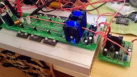
Also note C18, C19 - they were added earlier but they are not on the first version of the PCB. I keep them under the board for now - see the photo.
Removed the caps in parallel with R17, R18.
R19, R20 value is slightly increased to match the current settings of the non-switching OPS. Jeff - these values will be good for your "bundle".
Also note C18, C19 - they were added earlier but they are not on the first version of the PCB. I keep them under the board for now - see the photo.
Attachments

CDC-VFA-CCS + Non-switching OPS
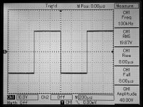
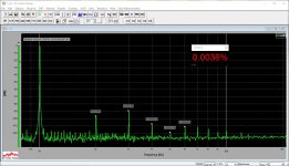
Live measurements for the tiny VFA front-end. This is actually a CFA-fast VFA.
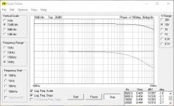
Slew rate and clipping are slightly asymmetric due to the single-ended VAS topology, however the overall performance is excellent. Note the great phase response on the bode plot.
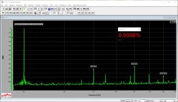
As usual, the spectrums are taken at 50W @ 8 ohm load, square waves are 40V p-p. Power rails are +/-50V (+/-2).
Live measurements for the tiny VFA front-end. This is actually a CFA-fast VFA.
Slew rate and clipping are slightly asymmetric due to the single-ended VAS topology, however the overall performance is excellent. Note the great phase response on the bode plot.
As usual, the spectrums are taken at 50W @ 8 ohm load, square waves are 40V p-p. Power rails are +/-50V (+/-2).
Attachments
-
 10-bode-1MHz.JPG69 KB · Views: 895
 -
 DSC_0141.JPG429 KB · Views: 226
 -
 DSC_0139.JPG474.5 KB · Views: 228
 -
 DSC_0138.JPG487.3 KB · Views: 218
 -
 DSC_0137.JPG487.3 KB · Views: 364
 -
 DSC_0136.JPG440.6 KB · Views: 383
 -
 11-imd-14-15khz.JPG188 KB · Views: 831
 -
 10-thd-020khz.JPG176.9 KB · Views: 823
 -
 10-thd-010khz.JPG176.3 KB · Views: 856
 -
 10-thd-001khz.JPG187.5 KB · Views: 891
I've lost track. Has anyone gotten Tubie running yet?
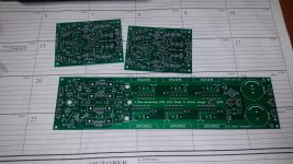
I mean - this bundle, on the picture. Yes - too many options 😛
Attachments
I mean - this bundle, on the picture. Yes - too many options 😛
Too many Sankens on one board.😀😀😀🙂
Nice looking pcb!!!I mean - this bundle, on the picture. Yes - too many options 😛

Last edited:
I see,i see all these my friend ,congratulations!
Hi, on the schematic in post #348:
http://www.diyaudio.com/forums/soli...e-old-ideas-1970s-ips-ops-35.html#post4554894
the one sensing for bias setting Is Q3.
Q4, Q5 are also on the heatsink, adjusting the clamping voltage.
Thanks i noticed at least my supposedly "official" SPICE models 2SC2922 / 2SA1216 are entirely wrong. Take care. Very good that you test the real amp! the sim will come out by far too good.
Thanks i noticed at least my supposedly "official" SPICE models 2SC2922 / 2SA1216 are entirely wrong. Take care. Very good that you test the real amp! the sim will come out by far too good.
I've got the good models of NJW3281/1302, that I use for simulations in such cases. They are rather close in the key parameters and both work well in the real prototype. Well, Sankens allow more power.
I've got the good models of NJW3281/1302, that I use for simulations in such cases. They are rather close in the key parameters and both work well in the real prototype. Well, Sankens allow more power.
MJL3281AG+MJL1302AG or MJL4281AG+MJL4302AG (a little more powerful, than 3281+1302), like me much more, than 2SC2922+2SA1216 (and 2SC3264+2SA1295).🙂
- Home
- Amplifiers
- Solid State
- Revisiting some "old" ideas from 1970's - IPS, OPS