They all have roughly the same temperature coefficient, ie they all work. I built a point to point one a while ago and only recently got around to doing a proper pcb. All devices are matched and ready to go. Hopefully finish mine tonight (no positive feedback in mine though, I used alternative method)It would be nice to know which lateral fets Papa decided to use. My guess is that 2SJ162 and 2SK1058 would work, since they have the desired temperature coefficients for operation without source resistors.
I'm fairly sure Papa has semelab lateral mosfets so highly likely BUZ series.
Last edited:
Or Alfet (ALF series) also made by Semelab.I'm fairly sure Papa has semelab lateral mosfets so highly likely BUZ series.
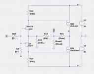
Here is schematic which appears to do the job. I have left the resistor values unspecified here to stimulate the DIYer to play around to find them. I have figured out a set of parameters that appear to meet most of the specifications that I will post at a later date. The primary spec that I haven't met is that my H2 is about 10dB too high which will require selecting jfets or lateral fets with different transconductances.
Attachments
Last edited:
Just a general comment.
I'd be very impressed/surprised if you could get stable operation of those lateral mosfets without any gate resistance.
I'd be very impressed/surprised if you could get stable operation of those lateral mosfets without any gate resistance.
Here is schematic which appears to do the job. I have left the resistor values unspecified here to stimulate the DIYer to play around to find them. I have figured out a set of parameters that appear to meet most of the specifications that I will post at a later date. The primary spec that I haven't met is that my H2 is about 10dB too high which will require selecting jfets or lateral fets with different transconductances.
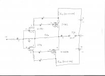
It is nothing new ,but is another way to get both negative & certain level of positive FB (bootstrap) for this simple A class symmetric PP amp.
Regards !
Attachments
Just a general comment.
I'd be very impressed/surprised if you could get stable operation of those lateral mosfets without any gate resistance.
You could be right about that. Are there any other output devices that could be used without gate stoppers and without source degeneration? I do not know how literally to takes Nelson's resistor count of 4+1. I had to add two more resistors of the JFET gates bringing the total to 4+1+2=7 resistors. If Nelson added gate stoppers to the laterals, that brings the total to 9 resistors?
mosfet gate resistors are conditio sine qua non , inherent thing ..... so , no need to count them
if there is any need to count anything

if there is any need to count anything
mosfet gate resistors are conditio sine qua non , inherent thing ..... so , no need to count them
if there is any need to count anything
We are playing Papa's game, without understanding the (complete) rules. 🙄
It is nothing new ,but is another way to get both negative & certain level of positive FB (bootstrap) for this simple A class symmetric PP amp.
Regards !
Have you tried to simulate that circuit? Positive feedback is needed to obtain a decent damping factor, but where is the positive feedback? The resistors between the output FET source pins and the power supply do not appear to do anything other than limit the output current.
We are playing Papa's game, without understanding the (complete) rules. 🙄
talk me about ......

OK , I'm dumb .... but it always ends Mighty ZM having twice parts more than Papa's
....... while Papa is ROFL for days
Have you tried to simulate that circuit? Positive feedback is needed to obtain a decent damping factor, but where is the positive feedback? The resistors between the output FET source pins and the power supply do not appear to do anything other than limit the output current.
No I did not simulate that circuit ,
but positive feedback(bootstrap) appears across both drain resistors of input JFets pair ,dynamically raising effective resistors values , and in that way raising OLG slightly ,
yes LatFet source resistors can lower DF , but for high-eff. LS with nominal 8-ohm or even better 16-ohm is not so big limitation .
Last edited:
No I did not simulate that circuit ,
but positive feedback(bootstrap) appears across both drain resistors of input JFets pair ,dynamically raising effective resistors values , and in that way raising OLG slightly ,
yes LatFet source resistors can lower DF , but for high-eff. LS with nominal 8-ohm or even better 16-ohm is not so big limitation .
It looks to me like those resistors just make to power supply more resistive without any other effect.
It is nothing new ,but is another way to get both negative & certain level of positive FB (bootstrap).
NP said the input fets are cascoded, and also that there is only one positive feedback resistor. This resistor connection
would then have to be symmetrical, so it would likely go from the output to the center of the bias circuit for the cascodes.
Also, the output devices are doubled, so there are 8 transistors total per channel.
"I created new printed circuit board artwork, adding cascode operation to the input stage and doubling up the number of output devices.
This version had a little more control, but still fell short. So... I broke the glass on the wall box labeled DESIGN EMERGENCY.
Inside was a single resistor labeled DANGER - POSITIVE FEEDBACK."
Last edited:
NP said the input fets are cascoded, and also that there is only one positive feedback resistor. This resistor connection
would then have to be symmetrical, so it would likely go from the output to the center of the bias circuit for the cascodes.
Also, the output devices are doubled, so there are 8 transistors total per channel.
"I created new printed circuit board artwork, adding cascode operation to the input stage and doubling up the number of output devices.
This version had a little more control, but still fell short. So... I broke the glass on the wall box labeled DESIGN EMERGENCY.
Inside was a single resistor labeled DANGER - POSITIVE FEEDBACK."
Rayma
You are right !
BTW , I guess that NP introduced positive FB from current sensing resistor source connected in series with LS .
I'd be very impressed/surprised if you could get stable operation of those lateral mosfets without any gate resistance.
Then you can be both. I have examples of just that, although as a pro forma
I always make space on the pc board for them.
😎
NP said the input fets are cascoded
If you re-read, you will see that I built versions with cascode and more output
devices, but went back to the original circuit.
😎
Rayma
You are right !
BTW , I guess that NP introduced positive FB from current sensing resistor source connected in series with LS .
Nope, read carefully:
Note the "I went back to the previous circuit", which was the non-cascoded circuit with only single output fets per rail.Inside was a single resistor labeled DANGER - POSITIVE FEEDBACK.
I went back to the previous circuit.
And I put that resistor in the amplifier...
ZM knows of tube circuits that have positive feedback - perhaps
he will post an example or two.
😎
he will post an example or two.
😎
Nope, read carefully: I went back to the previous circuit", which was the non-cascoded circuit with only single output fets per rail.
That "previous" didn't register with me. He did say that there is only one positive feedback resistor.
Last edited:
- Home
- Amplifiers
- Pass Labs
- First Watt F7 review