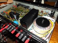
Toroid transformer finally put in and wiring secured in the RA-820AX.
Results are great:
DC stability is clearly better, no-load supplies are now +/-39V (up from +/-37v), main cap ripple less than 25mVac and below 5mV past the input stage filters. Absolutely no audible mechanical hum.
Bias stays solidly as set at 4 mV, and both heatsink and transformer temperatures stay cool at about 30oC. The hottest parts anywhere in the amp are now the speaker protection relays!
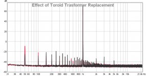
And best of all, the stubborn 50Hz peak on the spectrum which has frustrated me for so long - is now down by a whopping 18dB !!! (Red trace is "before", black "after")
Not sure whether it is a true representation of the tech difference between E-cores and Toroidals, or if the old Rotel tranny was actually already on the blink.
Anyway, I also tidied things up a bit and removed the experimental two-stage Miller feedback airwires to go back to a standard single 100pF, so THD went slightly back up from 0.0012% to 0.0015%.
You know, I can live with that - as I think that I could now officially claim to have The best Rotel RA-820AX anywhere on the planet! Yeah!
Per
Results are great:
DC stability is clearly better, no-load supplies are now +/-39V (up from +/-37v), main cap ripple less than 25mVac and below 5mV past the input stage filters. Absolutely no audible mechanical hum.
Bias stays solidly as set at 4 mV, and both heatsink and transformer temperatures stay cool at about 30oC. The hottest parts anywhere in the amp are now the speaker protection relays!
And best of all, the stubborn 50Hz peak on the spectrum which has frustrated me for so long - is now down by a whopping 18dB !!! (Red trace is "before", black "after")
Not sure whether it is a true representation of the tech difference between E-cores and Toroidals, or if the old Rotel tranny was actually already on the blink.
Anyway, I also tidied things up a bit and removed the experimental two-stage Miller feedback airwires to go back to a standard single 100pF, so THD went slightly back up from 0.0012% to 0.0015%.
You know, I can live with that - as I think that I could now officially claim to have The best Rotel RA-820AX anywhere on the planet! Yeah!
Per
Attachments
Last edited:
Hi Per,
Nice job! I like your work.
Hi 1210,
I can't agree more with Per on everything in his post. I especially agree that the 125 VAC cap should be replaced with one up to scratch! I'm surprised it hasn't shorted already (which would turn your amplifier on permanently). It may have burned the foil away though, so no or very low capacitance if it were to be measured.
-Chris
Hi Per,
Congrats on what is likely "The World's Best Rotel RA-820AX". May it deliver great listening pleasure to you and everyone around you 😀
I find it quite shocking how the switch to toroidal netted an 18dB reduction in 50Hz humm.
Hi Chris,
I'm also guessing the cap is toast by now as it has been subjected to twice it's allowed voltage for likely >1000h 😱. It beeing an MP Y-type, it likely just burned away internally instead of shorting. Lucky me. The order for a 300V AC Y2 MKP is aready out and it should be here this afternoon. That poor little 4A switch...the arcs it must've endured...
Maybe that also brings the turn-on thump down. Although that won't matter once the speaker-protection is mounted, it should still help the electronics by dampening the switching-transients.
BTW: your quoted paper doesn't distinguish between single- and multi-turn (non-rherostat) trimming potentiometers anywhere (other than, paraphrased, "unskilled people get better results faster and safer with multi-turns") and has the following to say about both:
I realize that that's not enough to ease your anti-multi-turn view (you got through experience and schooling I both lack), but it shows that it's safe in this application and I am not miss-using the part.
I also found a cheap but solid axle solution for the volume control space ploblem I might get - turns out a major german electronics supply store chain has everything I need except a 6mm metal axle (wich should be very easy to get elsewhere).
I'll try to get some measurements done, as soon as I have a test-jig soldered up and running. If my memory and google are correct, my Asus Xonar D2X sound card measures good enough (0.001% THD, 110dB SNR) to get an idea of what the current THD is. The specs call for 0.08% on the RA-820BX2. It'll be very interesting to see the effects of a re-routed ground, less gain, matched input pairs (again, thanks to you, good santa ) and VAS filtering. I'll post the results here if I manage to get some meaningful ones.
Since the R635 (R647 on the BX2) 0.22 ohm output resistance is outside/after the feedback-loop, am I right in saying that it's not needed when I substitute it for an inductor and put a zobel before it? PCB-space is rare on the RA-820BX2 and I am quite shure it doesn't do anything except lowering the damping factor and creating additional heat in the chassis, when the inductor+zobel are in place. Actually, I'm unconvinced it has any reason to be there at all, if it weren't for its residual inductance It certainly doesn't protect anything in case of a short circuit...
Kind regards,
1210
Congrats on what is likely "The World's Best Rotel RA-820AX". May it deliver great listening pleasure to you and everyone around you 😀
I find it quite shocking how the switch to toroidal netted an 18dB reduction in 50Hz humm.
Hi Chris,
I'm also guessing the cap is toast by now as it has been subjected to twice it's allowed voltage for likely >1000h 😱. It beeing an MP Y-type, it likely just burned away internally instead of shorting. Lucky me. The order for a 300V AC Y2 MKP is aready out and it should be here this afternoon. That poor little 4A switch...the arcs it must've endured...
Maybe that also brings the turn-on thump down. Although that won't matter once the speaker-protection is mounted, it should still help the electronics by dampening the switching-transients.
BTW: your quoted paper doesn't distinguish between single- and multi-turn (non-rherostat) trimming potentiometers anywhere (other than, paraphrased, "unskilled people get better results faster and safer with multi-turns") and has the following to say about both:
andIt can function as either a voltage divider or rheostat.
It directly contradicts you by saying it's unstable in rherostat applications without much current and safe in general rherostat applications.Stability is most often a concern when cermet trimmers are used in low current "dry" circuits (50uA amps and below). Under these conditions the contact resistance may vary, making the wiper appear unstable. This is most noticeable in some rheostat applications.
I realize that that's not enough to ease your anti-multi-turn view (you got through experience and schooling I both lack), but it shows that it's safe in this application and I am not miss-using the part.
I also found a cheap but solid axle solution for the volume control space ploblem I might get - turns out a major german electronics supply store chain has everything I need except a 6mm metal axle (wich should be very easy to get elsewhere).
I'll try to get some measurements done, as soon as I have a test-jig soldered up and running. If my memory and google are correct, my Asus Xonar D2X sound card measures good enough (0.001% THD, 110dB SNR) to get an idea of what the current THD is. The specs call for 0.08% on the RA-820BX2. It'll be very interesting to see the effects of a re-routed ground, less gain, matched input pairs (again, thanks to you, good santa
) and VAS filtering. I'll post the results here if I manage to get some meaningful ones.Since the R635 (R647 on the BX2) 0.22 ohm output resistance is outside/after the feedback-loop, am I right in saying that it's not needed when I substitute it for an inductor and put a zobel before it? PCB-space is rare on the RA-820BX2 and I am quite shure it doesn't do anything except lowering the damping factor and creating additional heat in the chassis, when the inductor+zobel are in place. Actually, I'm unconvinced it has any reason to be there at all, if it weren't for its residual inductance
It certainly doesn't protect anything in case of a short circuit...Kind regards,
1210
Hi 1210,
I'm not comfortable about removing that resistor as a manufacturer never installs a part unless there is some reason for it that is important. That's long experience talking. However, once you have it working properly you can try and remove it while watching for instability. An oscilloscope would be extremely handy for this portion of your repair. If you have a dummy load, put some capacitance in parallel with it. Try 0.22 uF or similar. You want to make certain the amp remains stable. You can try different values for this, lower or higher (but not much higher!).
Your matched pairs will really improve the sound quality, I'm glad you are trying it. I recently (during this thread life) matched over 20 pairs each of 2N5210 and 2N5087 for use in a badly designed Metaxis amplifier pair. This took days, but the matches will hopefully deliver on the promise of this "irreparable amplifier". With any luck, the servo can be removed, that circuit is also a disaster. The customer tried to have these amps repaired thrice with the manufacturer without success. It's time to change that game and admit the amp, as designed, is unreliable. Normally redesigning an amplifier isn't done. In this rare case it is warranted.
All I can do is mention this and point to some information on this topic. You can see that that application note doesn't really address this issue and much is left to interpretation. Coupled with a complete lack of any need to use a multi-turn control, you would normally install the same component type that was there and fits the pads. Certainly, this different control is not an upgrade at all. At the very best, it is a sideways move that doesn't fit in the mounting location properly. My biggest issue is the claim that the multi-turn control is an upgrade and that the single turn types are "cheap" and serve to save the manufacturer money. At least you know this is not the case at all.
-Chris
I'm not comfortable about removing that resistor as a manufacturer never installs a part unless there is some reason for it that is important. That's long experience talking. However, once you have it working properly you can try and remove it while watching for instability. An oscilloscope would be extremely handy for this portion of your repair. If you have a dummy load, put some capacitance in parallel with it. Try 0.22 uF or similar. You want to make certain the amp remains stable. You can try different values for this, lower or higher (but not much higher!).
Your matched pairs will really improve the sound quality, I'm glad you are trying it. I recently (during this thread life) matched over 20 pairs each of 2N5210 and 2N5087 for use in a badly designed Metaxis amplifier pair. This took days, but the matches will hopefully deliver on the promise of this "irreparable amplifier". With any luck, the servo can be removed, that circuit is also a disaster. The customer tried to have these amps repaired thrice with the manufacturer without success. It's time to change that game and admit the amp, as designed, is unreliable. Normally redesigning an amplifier isn't done. In this rare case it is warranted.
It is curious, but the transformer, or mounting, is defective. It the transformer case loses it's ground, this can happen.I find it quite shocking how the switch to toroidal netted an 18dB reduction in 50Hz humm.
It would normally reduce / eliminate the sharp "crack" of turn-off. You could also add a metal oxide varistor (MOV) directly across the primary, after the fuse and power switch. This will also help with turnoff noises, thumps and the like. It also provides line surge protection.Maybe that also brings the turn-on thump down.
You're right, but the multi-turn controls are used as potentiometers and the wiper circuit is supposed to carry uA or pA, not mA. The larger single turn controls are designed to better handle rheostat applications in the 100 ~ xmA current flow. Controls can have a lifetime, or "best before date". The single turn controls respond well to cleaning fluid. Multi-turn controls are generally sealed and full of lubricants. The smaller contact area really isn't designed to carry current, but the main track can dissipate power - but not the wiper circuit. I'll leave this up to you, but I have on the job training that is very specific about the use of these controls. Especially in the Metrology field (instrument calibration and service).your quoted paper doesn't distinguish between single- and multi-turn (non-rherostat) trimming potentiometers
All I can do is mention this and point to some information on this topic. You can see that that application note doesn't really address this issue and much is left to interpretation. Coupled with a complete lack of any need to use a multi-turn control, you would normally install the same component type that was there and fits the pads. Certainly, this different control is not an upgrade at all. At the very best, it is a sideways move that doesn't fit in the mounting location properly. My biggest issue is the claim that the multi-turn control is an upgrade and that the single turn types are "cheap" and serve to save the manufacturer money. At least you know this is not the case at all.
-Chris
Hi Chris,
I'll test the necessety of the R635 part later, then. Hopefully, this doesn't force me to "get creative" with any routing.
This wouldn't be the first time I encountered a component that has no reason to exist and/or is undersized/the wrong one to do its designated job properly...not even in this very amp...
I briefly "toyed" with the idea of a primary filter (10R + 0.22µF safety cap) to take some potential filtering-load and heat away from the transformers. But given the tiny chassis, the only solution to get rid of the potential heat would be a resistor in a transistor-package that's mounted to the chassis-backpanel (wich rings my "Unsafe!!"-alarm bells) and heatsinked from the outside.
The lack of space forces me to leave the primary as is, unless I want to add safety features in an unsafe manner. Something I'm not willing to do.
This could all be adressed properly, if the dual EI-cores were to be replaced with a single toroidal transformer, wich would free up more than enough space for everything. But unless the ones currently in there join the party where AngelP's dead one is dancing, that's not going to happen anytime soon.
I'll test the necessety of the R635 part later, then. Hopefully, this doesn't force me to "get creative" with any routing.
This wouldn't be the first time I encountered a component that has no reason to exist and/or is undersized/the wrong one to do its designated job properly...not even in this very amp...
I'm uncomfortable putting a varistor across the primary because there are no fuses on the primary and no space to put one in (that doesn't touch other components and isn't attatched to the removeable cover or even part of the mains cable outside the chassis). I looked around, but could not find schuko- or even euro-plugs with fuses (like the UK plug has it). I only found a coupling-plug with a fuse and a lot of them with surge protection and/or fault-current-detection. I could use 2 of them to fuse both live/neutral, but that would not only look tremendously stupid, but also cost >10 times what a standard internal solution does while still not beeing permamently attatched. So the only fuse on the primary is and remains the 16A mains fuse. 🙁You could also add a metal oxide varistor (MOV) directly across the primary, after the fuse and power switch. This will also help with turnoff noises, thumps and the like. It also provides line surge protection.
I briefly "toyed" with the idea of a primary filter (10R + 0.22µF safety cap) to take some potential filtering-load and heat away from the transformers. But given the tiny chassis, the only solution to get rid of the potential heat would be a resistor in a transistor-package that's mounted to the chassis-backpanel (wich rings my "Unsafe!!"-alarm bells) and heatsinked from the outside.
The lack of space forces me to leave the primary as is, unless I want to add safety features in an unsafe manner. Something I'm not willing to do.
This could all be adressed properly, if the dual EI-cores were to be replaced with a single toroidal transformer, wich would free up more than enough space for everything. But unless the ones currently in there join the party where AngelP's dead one is dancing, that's not going to happen anytime soon.
Hi 1210,
Completely understandable. I'm stunned that there isn't a mains fuse in the chassis, only the thermal fuses in the transformer primaries! Wow.
You should be listening to a nice sounding amp though. Enjoy!
-Chris
Completely understandable. I'm stunned that there isn't a mains fuse in the chassis, only the thermal fuses in the transformer primaries! Wow.
You should be listening to a nice sounding amp though. Enjoy!
-Chris
Well, I believe that credit is due where credit is due.
(OK, could someone please put that quote down to a deep, deep insight?)
The very reasonably priced toroidal transformer which I sourced through Maplin was apparently made by Vigortronics Ltd. I bow my head as I had actually never heard of that company before, even though they are just beyond Oxford in the UK.
Anyway, the tranny is really well built - double isolated primary leads and proper gauge secondary wires, etc. And the measurements seem to confirm the internal quality. Another thing that added to the total product was that the included neoprene anti-slid mounting washers were at least twice the normal thickness, giving added mechanical vibration insulation.
I have absolutely no personal affiliation or interest to declare, I just thought that a product that gives great quality for a very reasonable price tag deserves a mention and a due credit.
Per
So, the Rotel RA-820AX project is finished – and just in time for Christmas. I will put a “To Me from Myself” sticker on it and put it under the tree. And then (with due copyright credit to Chris' wife's bon-mot) I'll go “OH NO, you shouldn't have!” when the unwrapping time comes.
The original goal was to improve the THD by -20dB on a GBP 40 budget.
It ended up -26dB (or 20 times better than stock) – for a total of about GBP 60 due to the minor mains transformer mishap.
Now, to all those who – perhaps quite rightfully - claim that THD is really no measure of sonic or acoustic quality, could I maybe recommend the book: “Loudspeakers for Music Recording and Reproduction” by Phillip Newell and Keith Holland. It is one of the most insightful books I have read in a long time on the issue of subjective and objective acoustical assessment. It puts forward the idea that THD is “the top of the iceberg” of what we hear as “good” or “bad” sound reproduction.
And, if you bring down THD by reducing amp non-linearity (which is what I have done), you will also have greatly reduced the other gremlins (in particular IMD). I quote: “An increase in input signal which produces a negligible effect on low-order [harmonic] products can wake up the `evil forces` of nonlinearity, releasing an unfathomable number of high-order intermodulation product `piranhas` to tear the flesh of the reproduced sound to pieces”. Well, I couldn't have put it better myself.....
Anyway, “Well, How Does It Sound?” I hear you cry. As I have stated previously, I am really not very good at producing Hi-Fi press wooly superlatives, so let me try to perhaps give an analogy to how I perceive the “sound” of a non-modded Rotel amp to what I have now:
“Go out on a clear night in the suburbs of a city and look at the starry sky, and you may say: “Oh that's nice, look how many stars you can see!”. And then – with a few modded steps - go out in a dark field or a mountain desert and look up – and you will go “WOW!”
That's how it feels.
Merry Cristmas everybody!
Hi Per,
So. How do you like it after having it for a bit?
I agree with your take on the falling distortion numbers and strongly feel this is the case. The reality is that comparatively small changes in the numbers can make a huge difference in how it sounds. Of course there are also other tests you can perform too. I think you would have seen improvements with every metric as you did make the amplifier much more linear.
You have every right to feel proud of this accomplishment. You took methodical steps while recording each change. No magic parts. This is how improvements to existing equipment ought to be done. Not the wholesale replacement of capacitors with parts too large to fit properly.
Merry Christmas!
-Chris
Chris,
It is absolutely awesome. It still looks like as a nice Rotel, but it definitely no longer sounds "Rotel'ish", it is in a different league.
There is a completely new level of, well what can I say - "lack of effort" in delivering a deep, solid controlled bass without any audible influence on the rest of an amazing music frequency detail. Even my old Snell reference speakers sound like they have suddenly had a total new lease of life.
It actually reminds me of the unexpected surprise I had when I heard the difference between a Class A amp over my first 1975 "pride and joy" second hand Fisher TX-100 budget amp.
But don't take my word for it. My good wife (whom I admit to have submitted to listening to many of my more or less fickle audio experiments over the years) came into the room, sat down, listened to two Norah Jones tracks and said: "That's a keeper. Whatever you have done, don't ever sell that."
And I don't argue with wives - particularly not with mine.
Per
Hei Per,
I get you completely. I use the same test, my wife, and the same music. I also sometimes do similar things for customers. The parts might not add up to a lot, but the service time sure does doing these things.
There is nothing better than watching the surprise on a customer's face when they hear their new <whatever> after this kind of work. I had a strong feeling you would come back with the comments you did.
Right on Per!
-Chris
I'll see what I can do to make the primary side a little safer. As is, threre is no fuse, an underrated (125V AC) capacitor over the on/off switch and no filter.
I've opened pandora's box, haven't I?
1210,
I opened my RA-820BX2 "Pandora" this morning and have a few observations which may interest you:
The mains switch arc suppressor cap is a quality RIFA metallized paper type self healing, approvals and all, but it is indeed a 125Vac/250Vdc type and must definitely be replaced for our 240Vac mains territory.
RIAA stage coupling caps C405/6 are apparently specified as - and are indeed tantalum 4u7 - great caps, but not in the audio signal path and they should be replaced unless there is some intended "sound colouring". I would put in a film type or perhaps a slim 10uF Silmic on the solder side of the PCB to make more room for your bulky stepped resistor volume pot?
Also, someone please explain to me the thinking behind paralleling bog standard 20% high uF ac coupling electrolytics with expensive 2.5% 1nF polystyrene film types, PCB placement clearly looking as some kind of an afterthought. A band-aid for poor electrolytic audio HF coupling specs? Why not put in better quality coupling caps in the first place?
And C611 simply gave me the giggles (see the schematic).
The original power stage input caps are 1uF stacked PE film EPCOS - not pretty, but better than electrolytics. Your PP replacements are even better.
Now to the discussions on bias setting. I put on the RTA and measured the THD at 7 different mV settings. Here is what I got:
1.0mV - 0.0210%
2.0mV - 0.0108%
3.0mV - 0.0076%
4.0mV - 0.0066%
4.4mV - 0.0059% (the factory specified setting)
5.0mV - 0.0056%
6.0mV - 0.0058%
7.0mV - 0.0060%
So, there is nothing gained by setting the bias higher than the spec. At the recommended setting, the BANDO transformer does get slightly hotter than the (paltry) heat sink, but nothing serious.
Even though the THD figures actually look rather good, the actual spectrum trace is less so - looks a bit like a humpback whale with a giant spiky hedgehog on top. There is even a peak at 60Hz (and harmonics) which, being in a 50Hz territory somewhat puzzles me.
Anyway, I think that you have a great opportunity to vastly improve your Pandora Box by some or all of the mod stages. While it is tempting to "mirror" your mods, I will have to see if I have the time for it.
Cheers,
Per
Hi Per,
Some times you can reduce the THD readings by increasing the bias current, but this normally occurs with "unfortunate designs" where the circuit is never truly happy. Certainly a class "A" design will measure better at increasing standing currents but we'll call that a special case.
-Chris
Exactly!So, there is nothing gained by setting the bias higher than the spec.
Some times you can reduce the THD readings by increasing the bias current, but this normally occurs with "unfortunate designs" where the circuit is never truly happy. Certainly a class "A" design will measure better at increasing standing currents but we'll call that a special case.
-Chris
Oops,
I just realized that I made 8 bias current setting measurements.
That just goes to show that there are indeed Three types of people in this world -
Those who can count - and those who can't.
May the new year be kind to us all.😀
Per
I just realized that I made 8 bias current setting measurements.
That just goes to show that there are indeed Three types of people in this world -
Those who can count - and those who can't.
May the new year be kind to us all.😀
Per
I'll second that.
Re: the reduction of 50 Hz hum with the new xfmr in, I can only assume that stray fields which previously got into the circuit somewhere are much lower now (it can't come from the rectifier). Obviously a toroidal would suggest magnetic, but if the xfmr has a shield winding it may also be electric.
It may just have been ground loop noise from the measurement setup anyway (ground loops like picking up magnetic fields after all, not to mention the issue of capacitive coupling to the mains in the xmfr, the effect of which may vary depending on mains plug polarity and which tends to be combated using shield windings on circuit ground). Here's how I'd test for this:
1. Power off amplifier and allow caps to discharge thoroughly.
2. Short output terminals + and - with some sort of bridge.
3. Take measurement(s) of spectrum. Observe amount of mains hum and compare.
4. Undo step 2.
If the new xfmr is quiet, that's good. Large toroidals (especially 500 VA up) enjoy a reputation for liking to hum when there is significant DC / imbalance on the mains.
I'll second that.
Re: the reduction of 50 Hz hum with the new xfmr in, I can only assume that stray fields which previously got into the circuit somewhere are much lower now...
...Large toroidals (especially 500 VA up) enjoy a reputation for liking to hum when there is significant DC / imbalance on the mains.
Any toroidal will hum if there is a net DC field present in it's core as the core can easily get saturated. There does not have to be DS present in the mains, it's enough thet the currents drawn through the windings do not add to net zero between the positive and negative half-cycles of the mains. THis situation does happen dynamically as the current drawn varies with the output signal of the amp, which is why testing with dummy loads often tends to reveal a 'singing' transformer (and sometimes other parts but we are not talking about them now). However, the net DC in the audio signal should be zero so the core equalizes (demagnetizes) across multiple cycles of the mains.
I would wager the reduction of the 50Hz and harmonics is due to electrostatic shielding but also due to the reduction of the stray field generated in the peaks of the mains sine due to the old smaller core going near saturation during peak currents that charge the filter caps through the rectifier. A larger transformer is capable of higher peak currents to begin with.
Also, if it is wound with rectification on the secondary side in mind, rather than, say, driving an incandescent halogen lamp which is a pure resistor, it will be would for a lower flux density in the core, which equals to more turns per volt. This produces more headroom for peak rectification currents, and to an extent, DC imbalance - but the transformer ends up being larger, i.e. more expensive. This is incidentally why some people use vastly over-specified transformers WRT VA rating - to get the required maximum peak current by brute force, mostly to feed a lot of filter caps. However, optimizing for lower Bmax in the core gives a MUCH better behaved power supply (less stray fields, softer peaks on currents, less diode ringing etc) and can end up in a cheaper transformer if you can live with somewhat worse regulation (in many cases such a transformer has to supply a class A amplifier so this is not really an issue).
Thank you ilimzn, that could maybe explain the improvements by the toroidal.
However, I still have a hunch that the old Rotel e-core tranny may have been damaged. It has been too long since I studied the failure mechanisms of transformers, but I seem to recall that degradation and oxidation can be gradual for both the windings, internal solder joints and the thermal switch, leading to the formation of semiconducting or other weak spots and then to eventual failure when stressed?
Anyway, the ac mains quality in the UK is not very impressive or indeed EU standard 230V harmonized. This morning I measured 244Vac, -5.2Vdc (!) and lots of spiky noise.
On the positive side, I guess that makes the final RA-820AX rail supply noise immunity achievements even more impressive?
I'll see what I can do to make the primary side a little safer. As is, threre is no fuse, an underrated (125V AC) capacitor over the on/off switch and no filter.
I've opened pandora's box, haven't I?
1210:
I replaced the mains switch capacitor on my RA-820BX2 today, it is a RIFA part #PME265MA447 4.7 nF - or rather - it was.
The plastic casing is cracked and the capacitor is open circuit. How that 125Vac rated cap got through the EU safety approvals, I simply don't know.
Replacement type is a proper PME271 Y2.
Per
Last edited:
I got one of these here, MKP 300V AC Y2/X1 type. My old 125V AC one is just dead, but not shortened (as a Y-type ought to, when abused as is was).
I'm a bit baffled by your bias-related THD-measurements. The 820BX2 is advertised as <0.08% THD at 30W / 8 ohms output. Your measurements seem to show that it's actually 20dB better than that in your setup. At what output level and with what load did you measure?
I'm a bit baffled by your bias-related THD-measurements. The 820BX2 is advertised as <0.08% THD at 30W / 8 ohms output. Your measurements seem to show that it's actually 20dB better than that in your setup. At what output level and with what load did you measure?
- Home
- Amplifiers
- Solid State
- Improve a Rotel amp THD by 20dB!