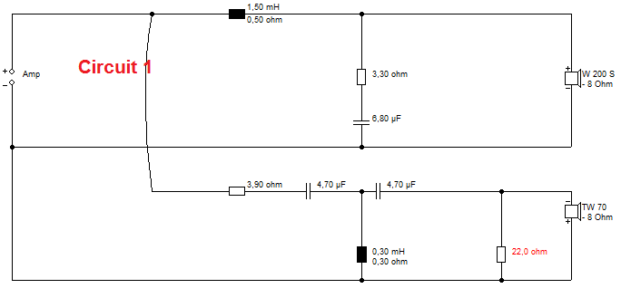
Here's two circuits I used recently on my speakers. Both BW3. Which one do you think sounded smoother and better?
I enclose the equipment on test. Usual Rotel SS amp and CD.
You are a very silly person. I like that. Here's my answers.
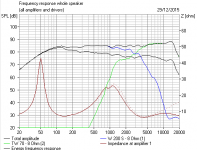
Circuit 2 may have more output especially between 2kHz and 5kHz, and the higher impedance overall but it also has the most severe impedance phase (40ish vs. 65ish) angle in the tweeter range. I'd be really curious actually to see if the amps pictured would have a difficult time with that or not.
Note the acoustical phase angle of the tweeter will be pretty close, with the biggest deviation being less than 10 degrees, but almost equal at the zero crossing, so that was a red herring. 🙂
Best,
Erik
My moniker, system7, is NOT a reference to new-age hippy Steve Hillage's musical group, or to the old Apple computer operating system. In fact it is a reference to my own engineering discipline which is Systems Engineering.
Let me explain it this way. The loudspeaker specialists could probably design a speaker which is measurably flat in every respect. The amplifier guys could probably make something that looks good on paper too. The computer modelling girls would do the crossovers. All would tend to cost overruns left to their own devices.
What the slightly exotic systems engineers do is look at the overall picture. We want a cheap system that is easy to make and reliable and non-toxic and testable. We don't get too bogged down in detail, but we do look at how the various disciplines interact into a whole.
In other words we want stuff that wins a cigar at every level. Like this one:
This one could ruin our corporate reputation:

I suspect that the specialist engineers got annoyed at what we did to their designs, but really we kept them in a job, and most important, upheld the companies' reputation for cheap and reliable products that satisfied at every level. 😎
Let me explain it this way. The loudspeaker specialists could probably design a speaker which is measurably flat in every respect. The amplifier guys could probably make something that looks good on paper too. The computer modelling girls would do the crossovers. All would tend to cost overruns left to their own devices.
What the slightly exotic systems engineers do is look at the overall picture. We want a cheap system that is easy to make and reliable and non-toxic and testable. We don't get too bogged down in detail, but we do look at how the various disciplines interact into a whole.
In other words we want stuff that wins a cigar at every level. Like this one:
This one could ruin our corporate reputation:
I suspect that the specialist engineers got annoyed at what we did to their designs, but really we kept them in a job, and most important, upheld the companies' reputation for cheap and reliable products that satisfied at every level. 😎
I love that.
I am also systems engineer lol (ESE)
Its less 'cigar at every level' and more 'System design from the mining the ore to the finished piece of jewellery' in my experience. A more generalised engineering discipline, covering a wider field of subject matter, and usually accompanied practical experience in a hands on fashion.
At least in my experience.
Last edited:
The issue I have described here is a purely practical one based on listening tests, which is what it's all about in the end. I've built dozens of crossovers along these lines.
This is not a tonal problem. I can correct that with a resistor change or the treble control of the amplifier. It seems to be, as I stated, the amplifier is, for whatever reason, sensitive to the load at supersonic frequency.
I hope you have read Lynn Olson on this subject:
http://www.diyaudio.com/forums/multi-way/100392-beyond-ariel-722.html
Notice that Lynn says some amplifiers are insensitive to this. Maybe ferrofluid tweeters have a path to ground at HF too. I don't know.
I'm really only interested in the takeaway that it matters with my equipment, and maybe yours.
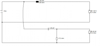
For interest, here is the filter of the famous old Mordaunt-Short MS10i designed by Robin Marshall AFAIK.
That little 2W 47R resistor always baffled me. Why was it there? 🙂
This is not a tonal problem. I can correct that with a resistor change or the treble control of the amplifier. It seems to be, as I stated, the amplifier is, for whatever reason, sensitive to the load at supersonic frequency.
I hope you have read Lynn Olson on this subject:
http://www.diyaudio.com/forums/multi-way/100392-beyond-ariel-722.html
Notice that Lynn says some amplifiers are insensitive to this. Maybe ferrofluid tweeters have a path to ground at HF too. I don't know.
I'm really only interested in the takeaway that it matters with my equipment, and maybe yours.
For interest, here is the filter of the famous old Mordaunt-Short MS10i designed by Robin Marshall AFAIK.
That little 2W 47R resistor always baffled me. Why was it there? 🙂
Attachments
It made the sound seem right to the Designer that would make the final speaker attractive to more potential customers.
It does come down to making the product as cheap as possible and still sell.
It does come down to making the product as cheap as possible and still sell.
Your answer to the 47R resistor is in post #20. Can also help to knock down the resonance impedance peak a tad if it's a minor problem without having to go the full LCR.
You really need a circuit 3 with the 1R given the flick and the 3R9 increased to 5R6 or whatever to bring the top end down to the level of circuit 1. With that change the rest of the filter should be recalculated to address the different method of padding and that should apply to circuit 2 as well.
I can see where the 22R could be handy with a cone tweeter (BTW, got a high Le=0.16mH..... I have mid woofers with lower Le).
The series xo in post #17 needs some work as the tweeter is only a few dB down at Fs. I know it's only there to show an impedance plot. For series xo's, the inductors need much lower DCR for tweeter protection (plenty of info about that online). An AR series xo would have been easier, less components but maybe not as much fun or challenge.
Really, rabbitz, I was just sharing an observation about supersonic electrical amplifier load to my good friends here at diyaudio.
Naturally I know how to adjust tweeter level, but my observation was really that the 22R shunt IMPROVES the sound with my particular amplifier. People using attenuators on the tweeter will have this built-in.
But I am now re-examining some circuits to incorporate this feature. For instance, Marco_Gea's nice two way might be improved:
http://www.diyaudio.com/forums/multi-way/147632-classic-monitor-designs-25.html#post4428857
After the holiday, I shall rebuild my take on his two way a bit like this:
I am thinking it will sound better. Nothing like a good theory, eh? Now to test it! 😎
The loudspeaker specialists could probably design a speaker which is measurably flat in every respect.
The amplifier guys could probably make something that looks good on paper too. The computer modelling girls would do the crossovers.
I find these kinds of comments somewhat offensive. Perhaps I speak for others as well.
While many diy-ers on this forum try to find a good balance between trade-offs in a design -- regardless of their special interest -- I find it difficult to believe that only certain "systems engineers" are capable of arriving at the "right" answer. Even good systems engineers can overlook important details with not so good results.
Like many others on this forum, I do appreciate the information sharing and collaboration that can be learned from it. Hooray to you for re-discovering the effect of the amplifier on speaker performance at higher frequencies, and thanks for sharing this information. But there is no need for the pompous, condescending attitude which is subtly conveyed here.
Dave R, I think you're just a bit sore you got the wrong answer! 😀
Funny how you now claim to have known the right answer all along. 🙄
So don't shoot the messenger. But it was a systems problem, nothing directly wrong with the amp or the speaker. Just they weren't playing together nicely.
I'd be interested in whether anyone else can confirm my findings. Or has tried, say 8 ohms shunt, or a zobel, or a bass tank, all of which should get to the same place of giving the amp a good supersonic load.
Steve, thanks for the insight into the day-to-days of a Systems Engineer. I was only talking to my daughter about perspective yesterday 😉
While I guessed right it was for the wrong reason. So what you are showing is a reason that some amps and speakers don't play well together, but I think it also says something for those that concern about the parasitics of cables and inductive resistors.
This is something I think about when I put on my amp builders hat (the one with the ground connection 😀), because I'd rather the HF amplifier loop remain small, and I alluded to this earlier in this thread. Do you notice an improvement putting the shunt resistor directly across the amp output terminals?
I find these kinds of comments somewhat offensive. Perhaps I speak for others as well.
While many diy-ers on this forum try to find a good balance between trade-offs in a design -- regardless of their special interest -- I find it difficult to believe that only certain "systems engineers" are capable of arriving at the "right" answer. Even good systems engineers can overlook important details with not so good results.
Like many others on this forum, I do appreciate the information sharing and collaboration that can be learned from it. Hooray to you for re-discovering the effect of the amplifier on speaker performance at higher frequencies, and thanks for sharing this information. But there is no need for the pompous, condescending attitude which is subtly conveyed here.
You sure don't speak for me! I find System 7's comments to be consistently clever as well as informative. I appreciate both here.
I believe the pomposity is hardly subtle and therefore meant to be ironic, and not directed at anyone. Lighten up a little.
Peace,
Tom E
Well, thankyou madisonears. I reread what I had written and it didn't seem in the least offensive to me. I have deep respect for the specialists, but the generalists can often say something about ALL systems that is useful. 😉
Information Theory says the information that a channel can convey depends solely on the bandwidth and signal to noise ratio, for instance. You actually don't give a hoot if it's a radio system or a hifi speaker and amp.
Modern audio designers pay little attention to signal to noise, and rarely measures it for, say, a soft dome tweeter. The fashion is THD. They should. White noise testing is very revealing in radio frequency channels.
That model of an amp with load is a simplification, of course, but I think explains the load and stabililty and noise problem. If all is well, cables and shunt resistors and HF quality won't matter. But sometimes it might, which is what AllenB is talking about.
So this little 68R resistor, or 7.5R + 1uF Zobel for all I care, does make a difference, but not always. Depends how the amp is designed.
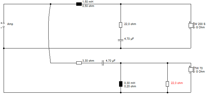
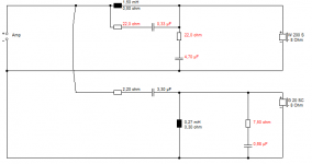
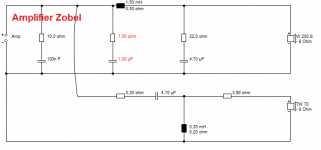
The red elements in the circuit below improve the sound with cheap amps IMO. Because they create a lowish resistance path to ground at HF.
Information Theory says the information that a channel can convey depends solely on the bandwidth and signal to noise ratio, for instance. You actually don't give a hoot if it's a radio system or a hifi speaker and amp.
Modern audio designers pay little attention to signal to noise, and rarely measures it for, say, a soft dome tweeter. The fashion is THD. They should. White noise testing is very revealing in radio frequency channels.
That model of an amp with load is a simplification, of course, but I think explains the load and stabililty and noise problem. If all is well, cables and shunt resistors and HF quality won't matter. But sometimes it might, which is what AllenB is talking about.
So this little 68R resistor, or 7.5R + 1uF Zobel for all I care, does make a difference, but not always. Depends how the amp is designed.
The red elements in the circuit below improve the sound with cheap amps IMO. Because they create a lowish resistance path to ground at HF.
Attachments
Yes, thank you madisonears, there is a world of confusion out there. We have an endearing catchphrase in Australia.. 'I like the boy'. One of our TV personalities was hosting an awards show with Mohammed Ali back in the day. To cut a long story short, the entire nation was waiting for it to be explained what went wrong that night.
Steve, have you seen anything to prove that shorting HF with a cap (after the choke//R and before the terminals) can help with some amplifiers?
Steve, have you seen anything to prove that shorting HF with a cap (after the choke//R and before the terminals) can help with some amplifiers?
I'd be a bit wary of shorting the HF with a simple cap, AllenB. Voltage amplifiers simply don't like driving short-circuit. Tends to strip the emitter disastrously. It'd be fine with a current drive valve amp, of course. Valve amps, by contrast, don't like driving open circuit.
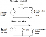
TBH, I really don't see much difference between a fast valve current amp and a fast MOSFET voltage semiconductor amp. I have become convinced by the mathematical Thevenin-Norton equivalents that they end up in the same place. I built a current-drive collector follower bipolar amp back in the day, but it tended to fry tweeters when they went high impedance, because feedback made it push more and more voltage to get the current up.
Regular transistor Class AB is voltage drive emitter follower.
Seems to me that the real problem is that amplifier manufacturers have to design for all sorts of speaker HF impedance. Maybe we should design for speakers to be largely flat 8 ohm load regardless.
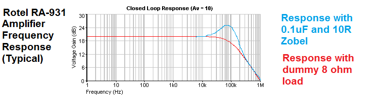
I could probably modify the Rotel RA-931 with a bigger Zobel at the output. It would be less crossover dependent. But also less efficient, dipping to 4 ohm load at times.
Let me reiterate that you folks with straight tweeter attenuators (the last image) really don't need to worry about this. HF Impedance remains fairly flat with a tweeter attenuator. 🙂
TBH, I really don't see much difference between a fast valve current amp and a fast MOSFET voltage semiconductor amp. I have become convinced by the mathematical Thevenin-Norton equivalents that they end up in the same place. I built a current-drive collector follower bipolar amp back in the day, but it tended to fry tweeters when they went high impedance, because feedback made it push more and more voltage to get the current up.
Regular transistor Class AB is voltage drive emitter follower.
Seems to me that the real problem is that amplifier manufacturers have to design for all sorts of speaker HF impedance. Maybe we should design for speakers to be largely flat 8 ohm load regardless.
I could probably modify the Rotel RA-931 with a bigger Zobel at the output. It would be less crossover dependent. But also less efficient, dipping to 4 ohm load at times.
Let me reiterate that you folks with straight tweeter attenuators (the last image) really don't need to worry about this. HF Impedance remains fairly flat with a tweeter attenuator. 🙂
Attachments
Last edited:
- Status
- Not open for further replies.
- Home
- Loudspeakers
- Multi-Way
- Which crossover sounds better?