Measure C902 , scope on AC, probe 10x, Volt/div at 1 or 2, Timebase 5mSec is ok.
I made a video this time.
https://youtu.be/UucE1OFUoJM
It's on 10X.
That's still major hum injected right into the output tube grids, The circuit doesn't use any more filtering, likely to make sure the grid bias reaches final voltage well before the filaments and plates fully conduct.
When I look to your video and the ripple voltage on C903 is 20 volts and there was no power given to the speakers, it's too high. So the C903 capacitor is not 80uF anymore. Also the ripple voltage you measured before on C906 is also much too high, so that capacitor is gone.
When those capacitors are replaced, the hum will also disapear. The smal signal what where moving around I think that is no problem. It's too less, because you switched the measuring voltage to a small value and then the movements are millivolts.
When those capacitors are replaced, the hum will also disapear. The smal signal what where moving around I think that is no problem. It's too less, because you switched the measuring voltage to a small value and then the movements are millivolts.

Ok so, I'm assuming c902-c905 is the can. Finding a can with those 4 exact values sounds like it will be hard.
Should I try to parallel the existing filter caps with fresh caps like Enzo recommended?
Should I try to parallel the existing filter caps with fresh caps like Enzo recommended?
Last edited:
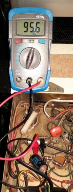
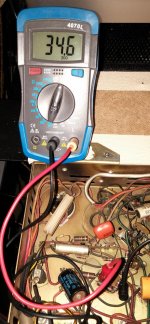
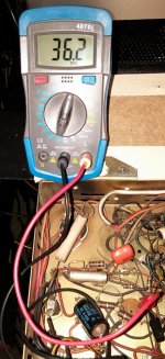
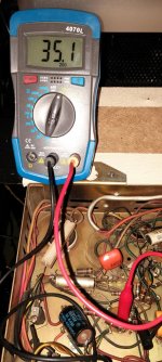
OK. I have just tested the cap values. The cans all check out. c906 does not have it's value.
File name corresponds with cap under test.
File name corresponds with cap under test.
Attachments
What did you do?
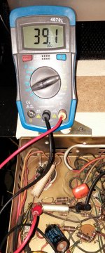
Sorry, I said it in the video. I replaced c906 that had the 39UF capacitance when it should have 100UF.
Video
https://youtu.be/BQcRH_ct43Y
That's very nice. Sorry, i did not looked at the video.
Succes with the amp.
Thanks for all the help! 🙂
OK so, check it out...
I picked up the R-3389A preamplifier off ebay for $28 shipped with the tubes.
Did you use the preamplifier in the end? If so, was it for a record player? Just wondering if it was a worthwhile purchase?
Question about the output transformer of this amp.
Being designed for commercial juke box installation, the OPT has multiple taps for different speaker setups. It also has a tertiary winding for 70v line output duty.
Now, the B+ is 365v, and the tertiary winding is center tapped (I.e. 35-0-35) and is therefore around 10% of the primary.
Could this winding be adapted for cathode feedback?
This has been the only Schematic that I have found that matches the schematics that were used on my r4359a. Do you by chance know where you got the schematic that is titled "Main-Amp-Comp"? I am restoring my amplifier with new resistors and capacitors, but I can't seem to find a parts diagram for this amp. Thank you for any help that you can provide!Hi,
I found the schema's, I hope they will help you repearing the amp. They did to me. 🙂
It was in 2015 so 8 years ago! 🙂 I think I repeared a jukebox from ROWE-AMI and I found the service manual in that time.
- Home
- Amplifiers
- Tubes / Valves
- Rowe R-4359A Amplifier