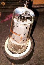
There should 7 tubes glowing. Which tubes are "off".
That youre protection light is on is normal (100 watt bulb ?) that its light is delayed could come from warming up the other tubes. Hum can come from unbalanced output tubes.
In the netherlands we say " Meten is weten 🙂 ". When you measure then you know.
It's a 250w bulb. It seems like all tubes are lighting up. It just seems like 2 of the 7868's are glowing much dimmer. However, other than the hum, the amp seems to be working as it should.
Check next post for video, almost done uploading.
R.
R-4359A Video
I made a little video of what it's doing. When you guys get a chance, please check it out.
Thanks!
R.
https://youtu.be/dwa7jqazt3U
I made a little video of what it's doing. When you guys get a chance, please check it out.
Thanks!
R.
https://youtu.be/dwa7jqazt3U
Do you have an oscilloscoop? because I think your capacitor C902 does not have its value.
Or a power tube mismatch. Please measure the ripple voltage there.
Or a power tube mismatch. Please measure the ripple voltage there.
OK, hum, as 60Hz is real hard to hear on computer speakers, and playing music over it makes it inaudible. Without reading back, are you SURE is it 60Hz rather than 120Hz? A scope will tell you instantly. If you don't NEED the music to demonstrate the problem, leave off the music.
The light bulb limiter is good for one thing, saving the amp from blowing fuses and excess current. if the amp was GOING to blow a fuse, the light comes on instead. If we no longer have a fuse blowing situation, GET RID OF the bulb. All the bulb does to a working circuit is cause low voltages and other issues. Plug into the wall now.
The amp hums, and hums through both channels. So either both channels have the same problem or something they have in common is bad.
So how clean is the power supply? How much ripple is on the 370v supply, or for that matter, how much ripple at pin 8 of the rectifier tube?
If you short the audio inputs to ground, does that leave the hum or diminish it? Most sure test is to tack solder a short wire right across th input jack. Your input seems to be from an iPod or something, so just to test that setup, unplug the inputs. Is the hum just as bad with empty jacks?
The bias supply is common, appears to be -35v on C906 in Mississippi's drawing.. How much ripple is there?
Do you have an oscilloscoop? because I think your capacitor C902 does not have its value.
Or a power tube mismatch. Please measure the ripple voltage there.
Unfortunately no. I don't have an oscilloscope. But it's on my list of things needed. I do have an LCR meter and did check all cap values and they all show the correct capacitance. I also noticed some diodes in there.
OK, hum, as 60Hz is real hard to hear on computer speakers, and playing music over it makes it inaudible. Without reading back, are you SURE is it 60Hz rather than 120Hz? A scope will tell you instantly. If you don't NEED the music to demonstrate the problem, leave off the music.
The light bulb limiter is good for one thing, saving the amp from blowing fuses and excess current. if the amp was GOING to blow a fuse, the light comes on instead. If we no longer have a fuse blowing situation, GET RID OF the bulb. All the bulb does to a working circuit is cause low voltages and other issues. Plug into the wall now.
The amp hums, and hums through both channels. So either both channels have the same problem or something they have in common is bad.
So how clean is the power supply? How much ripple is on the 370v supply, or for that matter, how much ripple at pin 8 of the rectifier tube?
If you short the audio inputs to ground, does that leave the hum or diminish it? Most sure test is to tack solder a short wire right across th input jack. Your input seems to be from an iPod or something, so just to test that setup, unplug the inputs. Is the hum just as bad with empty jacks?
The bias supply is common, appears to be -35v on C906 in Mississippi's drawing.. How much ripple is there?
@ 2:09 of my video I show the hum without the music.
I have no means to test ripple. The hum exists with or without anything connected to the inputs. Well, I guess I will have to either get a scope or give it to someone to test.
Thanks all for your help!
Rob
Here is a test for your volt meter. Set it to AC volts and measure a 9v battery with it that way. it will measure something for a moment but should settle down to zero volts AC. If your meter does that, it can be used to measure ripple. If the meter reads 9-10-12v or something on AC, then it will not measure ripple.
If it masses my test, then measure the bias supply and the B+ on AC volts. The result is the ripple.
In fact, even if your meter fails my test, you can still insert a capacitor - value not important, but a 0.1uf or 0.047uf would be preferred to something smaller - in series with your probe. That will allow AC through and block DC. et voila, AC ripple on DC meter.
Another simple ripple test is to parallel the existing filter caps with a fresh cap. if it improves the hum, then the hum was ripple.
The hum exists with or without something plugged into the input, but that is not the same as shorting the input. It is a valid test to make, and takes only a moment or two.
OK, looking at the 7868 prices, I'm being swayed into doing the 7591 conversion. Either by a quartet of these 1piece Gold Plated 7591 Adapter Top to RCA 7868 Tube Converter Adapter | eBay
or soldering in 4 8-pin sockets. On average the 7868 tubes are $25 each and the 7591 tubes are $10. I just bought 4 NOS Sovtek 7591s for $39.99.
So unless I get the preamp for this guy, I'm gonna go ahead and get rid of the unnecessary stuff like the relay and volume switch.
This is still up in the air. I may still just buy a 7868 if I can get an Amperex at a good price. I can even find one, period
OK so, check it out...
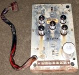
I picked up the R-3389A preamplifier off ebay for $28 shipped with the tubes. It's seen better days but it's got it where it counts. The seller said he tested it and it works. Even if it didn't work, it's worth that in the tubes alone. So I guess I'm gonna stick to the original plan. I just want to find an Amperex 7868. Having a hard time.
I picked up the R-3389A preamplifier off ebay for $28 shipped with the tubes. It's seen better days but it's got it where it counts. The seller said he tested it and it works. Even if it didn't work, it's worth that in the tubes alone. So I guess I'm gonna stick to the original plan. I just want to find an Amperex 7868. Having a hard time.
Attachments
OK, sorry it took so long to come back to this.
I have just tested the voltages on a few pins and they are a bit low.
Pin 8 of the 5U4 is stabilizing around 300VDC. However, Pin 4 and 6 are 600VAC (Supposed to be 370VDC/320VAC)
Pin 1 of the 7868's are at 300VDC ( Supposed to be 370 VDC)
Pin 1 of the 12AX7s are 100VDC ( Supposed to be 130 VDC)
I just acquired an older oscilloscope. It's a Tektronix 422 analog 15Mhz in good working order. So I'm ready to test further if necessary.
Let me know what you think about the low voltages and which components I should test.
Thanks!
Rob
I don't worry too much if the voltages are off, they can vary quite a bit. Components age, tube conduction varies. I only concern over it if there is a performance issue I can pin to them.
So should I try to start measuring ripple at C906? Do I measure across the capacitor or one side to chassis ground?
Here is a test for your volt meter. Set it to AC volts and measure a 9v battery with it that way. it will measure something for a moment but should settle down to zero volts AC. If your meter does that, it can be used to measure ripple. If the meter reads 9-10-12v or something on AC, then it will not measure ripple.
If it masses my test, then measure the bias supply and the B+ on AC volts. The result is the ripple.
In fact, even if your meter fails my test, you can still insert a capacitor - value not important, but a 0.1uf or 0.047uf would be preferred to something smaller - in series with your probe. That will allow AC through and block DC. et voila, AC ripple on DC meter.
Another simple ripple test is to parallel the existing filter caps with a fresh cap. if it improves the hum, then the hum was ripple.
The hum exists with or without something plugged into the input, but that is not the same as shorting the input. It is a valid test to make, and takes only a moment or two.
..and going back to one of your replies, should I implement some of these ideas with the oscilloscope?
Hi,
You measured 600 Vac at 4 and 6 of the 5U4, if you measured this with a reference at the chassis then it was 2 x 300 Vac and that is correct. Normally you do all measurements with one lead at chassis level.
When this is correct your outputvoltage at the first elco shoud be about 350 volts DC. This depends on current consumption, Ri of transformer etc.
When your first capacitor is bad, there is a high ripple voltage there and the avarage voltage there drops.
Please measure with your oscilloscope the ac ripple voltage there. Use a probe that can do this (1:10) and show us the result.
Hi,
You measured 600 Vac at 4 and 6 of the 5U4, if you measured this with a reference at the chassis then it was 2 x 300 Vac and that is correct. Normally you do all measurements with one lead at chassis level.
When this is correct your outputvoltage at the first elco shoud be about 350 volts DC. This depends on current consumption, Ri of transformer etc.
When your first capacitor is bad, there is a high ripple voltage there and the avarage voltage there drops.
Please measure with your oscilloscope the ac ripple voltage there. Use a probe that can do this (1:10) and show us the result.
Unfortunately, I am learning this oscilloscope, I'm am not sure what setting to use to look for ripple. Here is what I came up with, let me know what settings on the scope to use.
C906 / probe @10x to chassis.
Attachments
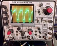
Here is what I came up with..
The picture suggests your probe is set to 1x magnification. Assuming display magnification is off that's 25 V p-p ripple across a bias first stage supply, which the schematic specs at -35 V dc. Is the scope's ground clip connected to chassis? If so C906 appears to be pooched.
The picture suggests your probe is set to 1x magnification. Assuming display magnification is off that's 25 V p-p ripple across a bias first stage supply, which the schematic specs at -35 V dc. Is the scope's ground clip connected to chassis? If so C906 appears to be pooched.
Yeah. It's on 10X. Mag is off. Ground clip to chassis.
- Home
- Amplifiers
- Tubes / Valves
- Rowe R-4359A Amplifier