It doesn't matter whether the heater is 'above' or 'below' the cathode. With a large elevation voltage like +/-75V the hum reduction is pretty much the same either way. You don't need two separate heater windings. Just elevate to 75V and stop worrying.
I don't get it. Like I said before, if you have a common heater supply lifted to +75V, the first stage has its cathode at +75V from the heater supply (which is fine) and the second stage has its cathode at -75V from the heater supply (which is also fine). The maximum cathode-to-heater voltage is 100V DC in either direction.
I don't understand why having the first stage cathode at +4V or whatever DC from the heater is better (or even much different) than having that first stage cathode at +75V from the heater. Do I have something to learn here?
--
There was an article* that claimed to show that raising the heater supply +60V above ground reduced coupling from heater-to-cathode and therefore reduced hum at the output. Since the first stage would be prone to hum pickup, it seems raising the heater supply +75V would be a good thing. However, as always, I could be wrong.
* The Valve Wizard has that article as a footnote. Cooper, C. E. (1944). Valve Hum. Electronic Engineering, (July), pp72-5.
--
In this situation it was a matter of preference not necessity putting the same roles in one tube. I will elevate both tube's heaters to 70-75V and that's that. Just that I preferred having two cathodes in a tube having the same voltage to the heater. Nothing to do with what's actually happening, just a personal preference.
There's something with this site and pictures, I *******************************************
[/CODE]
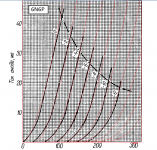
Here is a very good model for 6N6P model generated a real tube with a uTracer, it may be helpful:
.SUBCKT 6N6PLMO 1 2 3 ; P G C (Triode)
+ PARAMS: MU= 17.136 EX= 1.666 KG1=787.5 KP=84.0
+ KVB=3.75 VCT=0.00625 RGI=1000
+ CCG=18P CGP=8P CCP=17P
E1 7 0 VALUE={V(1,3)/KP*LOG(1+EXP(KP*(1/MU+(V(2,3)+VCT)/SQRT(KVB+V(1,3)*V(1,3)))))}
RE1 7 0 1G
G1 1 3 VALUE={(PWR(V(7),EX)+PWRS(V(7),EX))/KG1}
RCP 1 3 1G ; TO AVOID FLOATING NODES IN MU-FOLLOWER
C1 2 3 {CCG} ; CATHODE-GRID
C2 2 1 {CGP} ; GRID=PLATE
C3 1 3 {CCP} ; CATHODE-PLATE
D3 5 3 DX ; FOR GRID CURRENT
R1 2 5 {RGI} ; FOR GRID CURRENT
.MODEL DX D(IS=1N RS=1 CJO=10PF TT=1N)
.ENDS
Watch the image superposition over the data sheet.
Attachments
Last edited:
Thank you Mr. Lazaroiu!
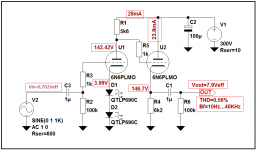
This should be the final schematic.

I will use TIP50 transistors for the HV regulator (or other recommended ones?). The voltage reference will be a LM329. HV reg transistor dissipates 2W, the first mosfet from the plate CCS dissipates 4W, and the one from the cathode CCS dissipates 3.5W.
Sim shows this voltage present on the output right after start-up. Should I worry?

The heaters PS will be a classic regulated with lm317, elevated at 70V.
Anything wrong with the way I implemented the HV regulator? I copied it from SY's phono preamp article: His Master's Noise: A Thoroughly Modern Tube Phono Preamp - diyAudio
This should be the final schematic.
I will use TIP50 transistors for the HV regulator (or other recommended ones?). The voltage reference will be a LM329. HV reg transistor dissipates 2W, the first mosfet from the plate CCS dissipates 4W, and the one from the cathode CCS dissipates 3.5W.
Sim shows this voltage present on the output right after start-up. Should I worry?
The heaters PS will be a classic regulated with lm317, elevated at 70V.
Anything wrong with the way I implemented the HV regulator? I copied it from SY's phono preamp article: His Master's Noise: A Thoroughly Modern Tube Phono Preamp - diyAudio
Attachments
Hello ,
I build a very simple preamp with four 6N6 systems parallel :

Measurements with Rohde + Schwarz UPL :
Load resistance 10 K


..........and now with 600 ohm


Kind regards , Alexander .
I build a very simple preamp with four 6N6 systems parallel :
Measurements with Rohde + Schwarz UPL :
Load resistance 10 K
..........and now with 600 ohm
Kind regards , Alexander .
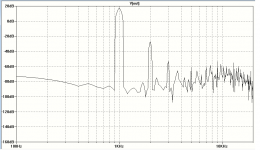
I seem to be having some problems with the frequency response of the amplifier when using the two-transistor regulator in the power supply.
It looks like this:

While bypassing the power supply with an "ideal" voltage source I get the following result that looks much better:

Am I doing something wrong in the power supply section?

Seems there is a problem with using a sine + rectifying bridge in the PS.
Using a voltage source instead makes the frequency response better again.
Why would that happen?
It looks like this:
While bypassing the power supply with an "ideal" voltage source I get the following result that looks much better:
Am I doing something wrong in the power supply section?
Seems there is a problem with using a sine + rectifying bridge in the PS.
Using a voltage source instead makes the frequency response better again.
Why would that happen?
It is effectively running the simulation at the moment of start up, before the power supply has stabilised.
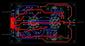
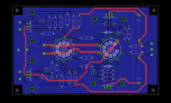
Is this a (good) star grounding layout?
I will have the to220 devices/heatsinks and big output caps on the backside of the pcb, so I can level the sockets to the top plate.
Since I want a homebrew type pcb, I had to design it in such a way that I can solder both sides where I have layer passings.
I highlighted the ground path. The tubes shields are tied together with the output resistors / output ground connection. Should I separate them as well?
Attachments
Is this a (good) star grounding layout?
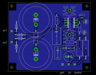
When using such small pcb you do not need to star ground inside the pcb.
Just make component side solid ground.
I have done this way with many amplifier boards including RIAA and all are hum free.
But make openigs at the attaching screw holes. Those should not be in contact with the gnd foil of the pcb.
Like this:
Attachments
Last edited:
When using such small pcb you do not need to star ground inside the pcb.
Just make component side solid ground.
I have done this way with many amplifier boards including RIAA and all are hum free.
But make openigs at the attaching screw holes. Those should not be in contact with the gnd foil of the pcb.
Ah, OK then.
I'll leave some clearance on the mounting holes as to not make ground loops.
Should the power supply be as well? With ground plane?
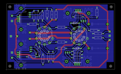
Yes it looks OK, but make sure you have at least 0,8 mm clearance between tracks and GND-foil, when there is voltage more than 100 V. Now it looks that there is not.
This should be with 0.8mm spacing.
I'm going to clean it off a bit and send it for making.
I still need to source pcb sockets that can be soldered on both sides.
Something like the one attached.
Is there a certain standard name for the pins layout? Something like "novar pcb socket" ? I want to search for them on ebay so I crosscheck the dimensions I have on the pcb.
** nevermind, I found the socket type: gzc9-a and gzc9-y.
Attachments
Last edited:
What is the impedance of the preceding amp? Maybe you should rearrange the value of the output cap.
http://www.diyaudio.com/forums/tubes-valves/172604-cathode-follower-output-cap.html
http://www.diyaudio.com/forums/tubes-valves/172604-cathode-follower-output-cap.html
I don't know. I think my friend has a Cambridge Audio P500, and the source he's using doesn't have much oomph.
That begs the question, why not?
What is the source? What is the source's output impedance? If it's a digital source, then it should put out 2V RMS signal at 0dBFS. If it's an analog source, then there is no standard.
What is the amp's sensitivity? (At what input voltage does the amp reach full power or clipping?)
What is the amp's input impedance?
--
- Home
- Amplifiers
- Tubes / Valves
- 6n6p preamp. Does it look ok?