All I could find on the P500 is that it has an input impedance of 47K. Don't know the sensitivity. It's source I think it's one of those bluetooth fm radio modules from ebay. I have played with one and I think I remember it's output being low. The P500 is a power amp only, no preamp stage.
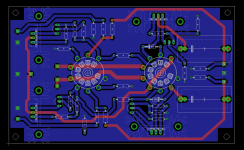
Anyway I added a larger footprint just in case a 2.2uF value for the output cap is needed. The layout will remain basically like this, maybe I'll just do some micro-adjustments for pads hole size and stuff like that. I sized the parts accordingly to what I have available /what I can source.
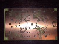
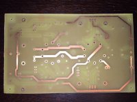
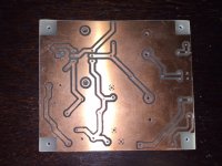
Managed to get the pcbs from the local guy. He did a good job, just need to enlarge the holes in some places, and check the ps board. But seems ok. The sockets are on their way. Need to order the parts next year + transformer. Will update after I install everything.
Anyway I added a larger footprint just in case a 2.2uF value for the output cap is needed. The layout will remain basically like this, maybe I'll just do some micro-adjustments for pads hole size and stuff like that. I sized the parts accordingly to what I have available /what I can source.
Managed to get the pcbs from the local guy. He did a good job, just need to enlarge the holes in some places, and check the ps board. But seems ok. The sockets are on their way. Need to order the parts next year + transformer. Will update after I install everything.
Attachments

About 6n6p oscillation, this tube need grid stopper? I see 10k in this design, this value is bigger than most problematic pentodes strapped as triodo with 1k or less are under control, more experiences with different values as grid stopper.
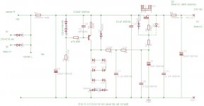
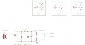
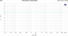
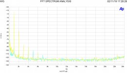
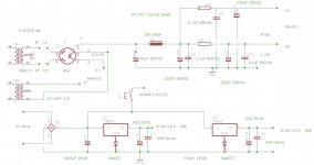
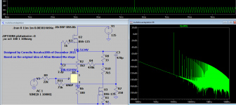
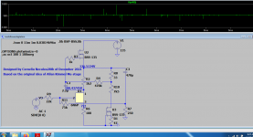
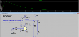
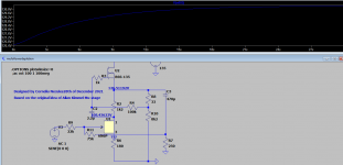
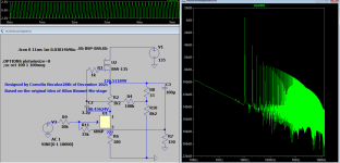
Hi this project with 6N6 was presented on Audioreview magazine just two months ago. It is simple but well dimensioned. There is a fixed bias come from a neg. regulator done with 7906. The Ia is set to 8 mA each section. There are two power supplies , tube and ss. It is possible to switch from one to another by three relè just for fun. In attach also the freq. response and FFT at 2 vout. I have other tests done. The sound it is very good.
Walter
Walter
Attachments
I chose 1K5 grid stoppers for my 6N6P preamp; and 100 Ohm anode stoppers.
Anode stoppers😀
Yes, 100V is the limit of Vhk.
Forgot, last question.
How should I use the tubes? One for each channel or one for each role?
Not sure if it matters in practice, but the tube data says:
6N6P, 6N6PI (6H6n, 6H6nN)
output 1st triode 1.7
output 2nd triode 1.85
(no denomination given)
The two halves are not completely identical it seems.
Anode stoppers😀
Mounted on the tube socket, because the actual anode resistor is too big, it is mounted a bit further down the block. This is the third version of my preamp: I've had some trouble with oscillation earlier, doing my best now to avoid that 🙂
Bonjour, j'ai construit un prototype. C'est le même schéma que Trileru avec quelques petites différences : tension d'alimentation 150v régulée avec un tube à gaz SG1 P ev. La résistance de la boucle de rétroaction est de 75 kΩ au lieu de 82 KΩ. le gain est de 5. J'ai fait des tests avec des résistances de sortie de différentes valeurs : 47, 100 et 120 kΩ. Avec 47kΩ j'ai un déphasage, 100kΩ un peu moins, 120kΩ en plus c'est très léger mais toujours présent. Cela compromet-il le bon fonctionnement, s'il vous plaît ? Les salutationsMerci M. Lazaroiu !
Cela devrait être le schéma final.
J'utiliserai des transistors TIP50 pour le régulateur HV (ou d'autres recommandés ?). La référence de tension sera un LM329. Le transistor HV reg dissipe 2W, le premier mosfet de la plaque CCS dissipe 4W et celui de la cathode CCS dissipe 3,5W.
Sim affiche cette tension présente sur la sortie juste après le démarrage. Dois-je m'inquiéter ?
Les radiateurs PS seront un classique régulé au lm317, élevé à 70V.
Y a-t-il un problème avec la façon dont j'ai implémenté le régulateur HT ? Je l'ai copié de l'article de SY sur le préampli phono : His Master's Noise: A Thoroughly Modern Tube Phono Preamp - diyAudio
Attachments

In all honesty , this design looks like a complete waste of resources...Either you're using one single dn2540 device or just one 6n6p ...that is all you need for a buffer in front of your power amp...If you're doing it with tubes you want that compression effect, and that is possible to get with one single 6n6p tube loaded with resistors. 6n6p is fantastically linear in the audio range loaded with resistors only. Besides 16ma/110v AK/-3v GK is the best point for 6n6p. If you need second harmonic, one single dn2540 is perfect for that.You just need to find the right bias for it.Bonjour, j'ai construit un prototype. C'est le même schéma que Trileru avec quelques petites différences : tension d'alimentation 150v régulée avec un tube à gaz SG1 P ev. La résistance de la boucle de rétroaction est de 75 kΩ au lieu de 82 KΩ. le gain est de 5. J'ai fait des tests avec des résistances de sortie de différentes valeurs : 47, 100 et 120 kΩ. Avec 47kΩ j'ai un déphasage, 100kΩ un peu moins, 120kΩ en plus c'est très léger mais toujours présent. Cela compromet-il le bon fonctionnement, s'il vous plaît ? Les salutations
Merci pour votre réponse.
Le point de fonctionnement est -2v 20ma.
Le CCS à l'anode fonctionne bien.I keep it.
J'ai essayé une résistance suiveuse de cathode 5,1k et un ccs.Je ne vois aucune différence avec mon oscilloscope.
But some wrote that it sounds better.
Regards
Le point de fonctionnement est -2v 20ma.
Le CCS à l'anode fonctionne bien.I keep it.
J'ai essayé une résistance suiveuse de cathode 5,1k et un ccs.Je ne vois aucune différence avec mon oscilloscope.
But some wrote that it sounds better.
Regards
The real trouble with these depletion mode mosfets when paired with tubes is that operating them at such low currents (for the mosfets current capabilities ) and especially at low VDS when you have one of them cascoded, puts them in very unfavourable working modes where you don't even get graphics in datasheet and some of the parameters importance isn't obvious with usual simulations.
There's not a single proof that one single dn2540 sounds worse than a cascoded one, they are fairly low capacitance and very high speed.Driving one with an op-amp makes it as fast as can possibly be for audio range reproduction but there's a lot of folklore outhere...
Just in case youthink i don't know what i'm talking about, in 2018 i made tons of simulations around a design based on bsp135 and d3a and i remember very well that there were two very distinctive working points , probably around the Miller plateau depending on The V DS applied over the bsp135 and measurements confirmed the difference seen in the simulation.From what i can remember is that you don't really want depletetion mode mosfets operating at low VDS just around the Miller plateau . https://www.diyaudio.com/community/threads/1v2-phono-riaa-preamplifier.315824/#post-5561159
Last edited:
@Marco audio Ceci est un forum Anglophone seulment. SVP faites vos posts en Anglais, ne pas en Francais.
Marco, this is an English language forum. Please make your posts in English. Any more posts that are uniquely en Francais will be deleted.
MdA.
Marco, this is an English language forum. Please make your posts in English. Any more posts that are uniquely en Francais will be deleted.
MdA.
Hello, is it now written in english ?
Before i don't had this trouble.I could activate the translation and write in english.
Now i must unactivate the translation for write in english.
Is it a mistake ?
Things are more difficult today as before.
Regards
Before i don't had this trouble.I could activate the translation and write in english.
Now i must unactivate the translation for write in english.
Is it a mistake ?
Things are more difficult today as before.
Regards
Last edited by a moderator:
Hello, thanks for your reply.The real trouble with these depletion mode mosfets when paired with tubes is that operating them at such low currents (for the mosfets current capabilities ) and especially at low VDS when you have one of them cascoded, puts them in very unfavourable working modes where you don't even get graphics in datasheet and some of the parameters importance isn't obvious with usual simulations.
There's not a single proof that one single dn2540 sounds worse than a cascoded one, they are fairly low capacitance and very high speed.Driving one with an op-amp makes it as fast as can possibly be for audio range reproduction but there's a lot of folklore outhere...
Just in case youthink i don't know what i'm talking about, in 2018 i made tons of simulations around a design based on bsp135 and d3a and i remember very well that there were two very distinctive working points , probably around the Miller plateau depending on The V DS applied over the bsp135 and measurements confirmed the difference seen in the simulation.From what i can remember is that you don't really want depletetion mode mosfets operating at low VDS just around the Miller plateau . https://www.diyaudio.com/community/threads/1v2-phono-riaa-preamplifier.315824/#post-5561159
It's now difficult to understand you due to translation's trouble.
I think that i agree with you about the number of mosfets:Only one should be enough .
I tested with a single mosfet and the gain is the same as with two. However, it is much better than with an anode resistor. So I keep a ccs.
About the cathode follower ccs ,i want to keep it too (but with one mosfet only).
Somes demonstrated that response is better. Bandwidth is larger.
Do you agree ?
In my case what are reasons to keep a cathode resistor please ?
A dn2540 and a pot aren't so expensive...
It is true that I let myself be influenced by literature by testing complicated and perhaps unnecessary things. So today I would like to be right and not fall for the superfluous. Would you help me in this process please?
Complicated things need to be adressed accordingly...Although a cascode has wider bandwidth than a single transistor we should not forget that its use in audio was due to adress the phase response in circuits using big amounts of global negative feedback which is not the case here.Apart from that, cascode's bandwidth goes up to hundreds of megahertz which makes way to unwanted oscillations and very strict constraints about the wiring or pcb traces.Then having a cascoded ccs made out of two depletion mosfets working at way lower currents than the ones they are made for is just throwing the circuit in a very unpredictible zone even for a simulator.I don't even see the usefulness of these circuits...If you want to take benefit of some sort of tube compression you need them less linear, like heavily loaded with a much lower resistor or having their anode starved with low voltages or just biased at very high currents...
Last edited:
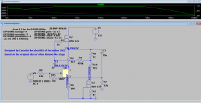
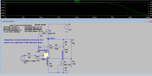
it took me a bit to play with that circuit again ...not really simple but you have here some simpler versions with fairly good results. They are much better for phono circuits with higher GM tubes though...
Attachments

Last edited:
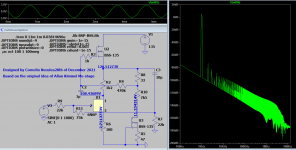
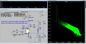
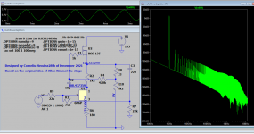
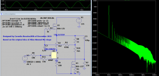
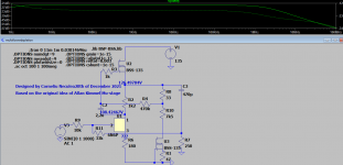
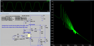
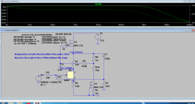
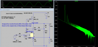
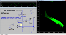
Now here's the thing with simulations...they don't always tell the whole truth unless you're a simulation professional which i am not so my only way to work around is to make a lot of them with different constraints rules i took from the www or remove them all together and see the difference and the difference is sometimesBIG.Thinking that 6n6p tube would be a waste just being used for a line output i considered raising the bar to a headphones amp output .32 ohms was way lower for a load so 250 ohms as my cans have looked like the next option but only the last two simulations confirmed results with or without constraints while the 250 ohms output worked with only one output capacitor, the 470uF giving the same wrong results with 220uF or 1000uF which makes me very suspicious actually about the accepted 470uF value because it might very well be a Happy resonace even though at 10khz still shows good results and I think that the real figure that tells you something is wrong is the DC plot at 0 v input.Few people built the Allan kimmel mu follower version anyway, cause anyone's trying to be original by using expired patents...butr when you're using the ccs loaded version i can tell you that you need about 30 seconds for this circuit to become stable at DC even with all heaters full on and every single time you fire it up it will find a different bias equilibrium...Yeah that is true, this is a fantastically good ac circuit if made properly, but the depletion mosfet is very prone to oscillations in the audio range or just above it in the ultrasound region and i can tell that because i built it , apart from that simulations will never give the final circuit...and that is the sad truth about weird circuits with both tubes and transistors.You need a littel bit of intuition ,some theoretical background about mosfets and a bit of luck to deal with them properly .
Attachments
-
 250hampA.png25.4 KB · Views: 101
 -
 250HampAbode.png20.4 KB · Views: 85
 -
 250HampB.png32.2 KB · Views: 95
 -
 250HampBbode.png47.5 KB · Views: 89
 -
 250HampWrongA.png25 KB · Views: 90
 -
 250hampWrongAbode.png26 KB · Views: 86
 -
 250hampWrongB.png34.3 KB · Views: 90
 -
 250hampWrongBbode.png21.9 KB · Views: 76
 -
 250hampX.png57.8 KB · Views: 85
 -
 250hampDC.png28.6 KB · Views: 85
 -
 dc1.png16.7 KB · Views: 71
 -
 dc2.png16.2 KB · Views: 101
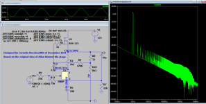
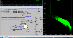
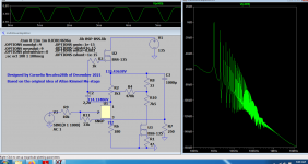
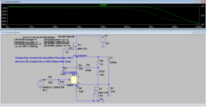
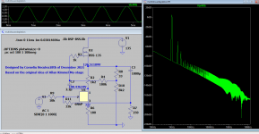
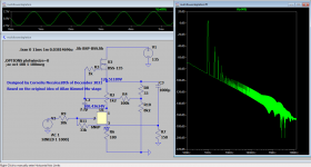
And here's why you can't get better with ccs loading the original Allan Kimmel circuit:
Attachments
-
 trueallankimmeldepletionA.png23.3 KB · Views: 133
 -
 trueallankimmeldepletionB.png26 KB · Views: 106
 -
 trueallankimmeldepletionC.png23.2 KB · Views: 98
 -
 trueallankimmeldepletionD.png25.5 KB · Views: 96
 -
 trueallankimmeldepletionE.png26.2 KB · Views: 101
 -
 trueallankimmeldepletionF.png21.9 KB · Views: 105
 -
 trueallankimmeldepletionG.png60.5 KB · Views: 114
- Home
- Amplifiers
- Tubes / Valves
- 6n6p preamp. Does it look ok?