Friend of mine got a power amp and wants a preamp, so I decided I'd build one with tubes.
I have a few 6n6p tubes around and I thought I'd put them to good use.
Also I have some 6n1p-ev and 6n2p-ev if they would be more suited for the job.
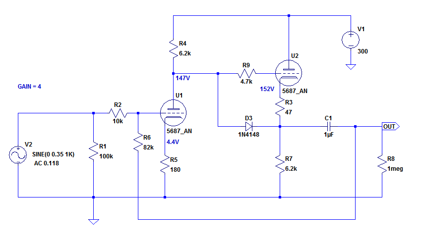
I made a sim of the schematic and seems ok. I made a DC-coupled cathode follower.
Did I leave something out? Any ways of improving this schematic?
The tubes operate biased about -4V, with 25mA and about 145V across them.
*** seems there's a problem with uploading files so I'll attach only the schematic, not also the sim file.

I have a few 6n6p tubes around and I thought I'd put them to good use.
Also I have some 6n1p-ev and 6n2p-ev if they would be more suited for the job.
I made a sim of the schematic and seems ok. I made a DC-coupled cathode follower.
Did I leave something out? Any ways of improving this schematic?
The tubes operate biased about -4V, with 25mA and about 145V across them.
*** seems there's a problem with uploading files so I'll attach only the schematic, not also the sim file.
Last edited:
A 5.6k plate load on U3 and 6.2k cathode load on U2 are awfully small in value, don't you think? Distortion will be fairly high, as will current going through the two 6N6P triode sections.
Did you run a test for harmonic distortion? There are a bunch of ways to do that, but here's one I like (enter it as a spice directive, Ctrl+S in LTspice):
--
One improvement could be using a DN2540 MOSFET constant current source as the load in the plate of U3.
You could also replace D1 and D2 with a 160R resistor, and leave it unbypassed. (25mA across 160R would give 4V at the cathode.) The resulting degenerative local feedback to U3 would reduce distortion, but would also reduce gain. You didn't mention how much gain you actually need.
Did you run a test for harmonic distortion? There are a bunch of ways to do that, but here's one I like (enter it as a spice directive, Ctrl+S in LTspice):
Code:
.options plotwinsize=0
.tran 0 100m 60m 1u
.four 1k 10 v(OUTPUT)
.OPTIONS numdgt=8.One improvement could be using a DN2540 MOSFET constant current source as the load in the plate of U3.
You could also replace D1 and D2 with a 160R resistor, and leave it unbypassed. (25mA across 160R would give 4V at the cathode.) The resulting degenerative local feedback to U3 would reduce distortion, but would also reduce gain. You didn't mention how much gain you actually need.
Last edited:
A 5.6k plate load on U3 and 6.2k cathode load on U2 are awfully small in value, don't you think? Distortion will be fairly high, as will current going through the two 6N6P triode sections.
Did you run a test for harmonic distortion? There are a bunch of ways to do that, but here's one I like (enter it as a spice directive, Ctrl+S in LTspice):
Code:.options plotwinsize=0 .tran 0 100m 60m 1u .four 1k 10 v(OUTPUT) .OPTIONS numdgt=8.
--
Most online reports say that 6n6p likes it at about 20-25mA 🙂
I ran the distortion and here's the results. The gain is too high, forgot about feedback. Need to make a few tests and come up with a small gain.

Can't figure out how to implement the feedback resistor as it's dc coupled and I have no output cap on the gain stage.
Can't figure out how to implement the feedback resistor as it's dc coupled and I have no output cap on the gain stage.
Figure 9 in this article:
https://www.aikenamps.com/images/Documents/anode.pdf
You could also use a 160 ohm resistor in place of D1 and D2, and leave it without a cathode bypass capacitor. That would introduce cathode degeneration, so local feedback. Gain would go down by about 1/3, from about 15x to maybe 10x. Would that be enough?
I ran a quick sim and found my distortion results were about like yours. At 1V RMS output, 0.1% THD, 2nd harmonic below -60dB, 3rd harmonic well down below -100dB. The distortion is cut in half with the unbypassed cathode resistor in U3 (at same output level, but higher input level due to lower gain).
--
Last edited:
Figure 9 in this article: https://www.aikenamps.com/images/Documents/anode.pdf
You could also use a 160 ohm resistor in place of D1 and D2, and leave it without a cathode bypass capacitor. That would introduce cathode degeneration, so local feedback. Gain would go down by about 1/3, from about 15x to maybe 10x. Would that be enough?
I ran a quick sim and found my distortion results were about like yours. At 1V RMS output, 0.1% THD, 2nd harmonic below -60dB, 3rd harmonic well down below -100dB. The distortion is cut in half with the unbypassed cathode resistor in U3 (at same output level, but higher input level due to lower gain).
--
I tried it only with the 160R resistor and the gain is about 8.7 . I was looking for 3-4 or so but this should be ok. Also with the mod in the link you put the thd looked very bad. Is an AC coupled variant better in the end if I manage to get to a gain of 4? The LEDs were something I found in the library, I was looking for 4V of drop.
A 5.6k plate load on U3 and 6.2k cathode load on U2 are awfully small in value, don't you think? Distortion will be fairly high, as will current going through the two 6N6P triode sections.
As far as I know, running the tube at higher current increases the gain and reduces distortion. Lowering the voltage across the tube + current increases the distortion. I don't know what other effect do the resistors have besides setting the operating points.
Thank's for the CCS tip. Do you have any resources for that? I still haven't decided which way I will go with the power supply. I guess a CRC filter.
**edit found plenty of ccs resources 🙂
Here's an anode follower circuit I whipped up using a 5687. Spice says it will have a gain of almost exactly 4x.
I used a 5687 model because I don't have a decent 6N6P model. If yours matches up well with real life usage, would you be able to share it? Thanks...
I used a 5687 model because I don't have a decent 6N6P model. If yours matches up well with real life usage, would you be able to share it? Thanks...
Last edited:
There's something with this site and pictures, I don't know why. I can't see the picture you added.
I found the model yesterday so I can't vouch for it.
Will tell you after I've done some tests on the breadboard.
I found the model yesterday so I can't vouch for it.
Will tell you after I've done some tests on the breadboard.
Code:
.subckt 6N6P 1 2 3
+ params: mu=18.8 ex=1.666 kg1=810 kp=85.5 kvb=600 rgi=2000 vct=.02
+ ccg=4.4p cgp=1.7p ccp=1.85p
e1 7 0 value=
+{v(1,3)/kp*log(1+exp(kp*(1/mu+v(5,3)/sqrt(kvb+v(1,3)*v(1,3)))))}
re1 7 0 1g
g1 1 3 value= {(pwr(v(7),ex)+pwrs(v(7),ex))/kg1}
rcp 1 3 1g
c1 2 3 {ccg}
c2 1 2 {cgp}
c3 1 3 {ccp}
r1 5 6 {rgi}
v1 5 2 {vct}
d3 6 3 dx
.model dx d(is=1n rs=1 cjo=1pf tt=1n)
.endsIt's this site and Google Photos. They don't work together. The schematic should display now.
In the sim, the distortion was reduced by 66% from the version with LED bias and no feedback loop.
Thanks for the model. Here's what I get with it:
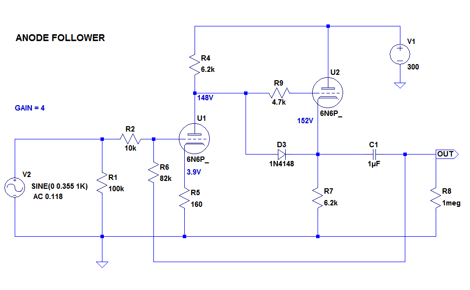
Gain is just about the same as with the 5687 model. Distortion is also very close. I get about 0.03% at 1V RMS output, but that's just a sim, not real life.
--
Running the tube at low voltages and high current will reduce voltage swing and steepen the loadline. But if you're only amplifying 0.5V input to 2.0V output, and since distortion is proportional to level when using triodes, it's likely that running a 6N6P at 150V on the plate and 20mA plate current might 'sound good.' The distortion looks acceptably low in the simulation.
I have a very simple 6N6P (originally 5687) preamp I built years ago. It's way overkill for a line amp. Too much gain, lots of plate current, too big, too heavy, runs too hot, etc.
I originally thought as you do, that pulling 20mA through the tube would sound better than less current. But I looked at loadlines and ran some simulations, and tried the more rational approach of striving to get the flattest loadline possible with passive components. In the end, a relatively high value load resistor of 15k coming from a +380V B+, and a plate current of about 15mA, sounded very good, smooth and clear to me. The relatively flat loadline predicted low distortion, and that did end up sounding good to me. I compared running with a couple of LEDs in the cathodes and running with an unbypassed cathode resistor (keeping the operating points constant). I wound up preferring the unbypassed cathode resistor (which was an option for me because my power amp has a high input impedance, so it presents a light load. If I was using a solid state power amp with a low input impedance of say 10k, I'd need to re-think that).
In the end, rebalancing the circuit for the flattest possible loadline sounded better to me than simply goosing the current ever upward.
YMMV, of course.
--
In the sim, the distortion was reduced by 66% from the version with LED bias and no feedback loop.
Thanks for the model. Here's what I get with it:
Gain is just about the same as with the 5687 model. Distortion is also very close. I get about 0.03% at 1V RMS output, but that's just a sim, not real life.
--
As far as I know, running the tube at higher current increases the gain and reduces distortion. Lowering the voltage across the tube + current increases the distortion.
I don't know what other effect do the resistors have besides setting the operating points.
Running the tube at low voltages and high current will reduce voltage swing and steepen the loadline. But if you're only amplifying 0.5V input to 2.0V output, and since distortion is proportional to level when using triodes, it's likely that running a 6N6P at 150V on the plate and 20mA plate current might 'sound good.' The distortion looks acceptably low in the simulation.
I have a very simple 6N6P (originally 5687) preamp I built years ago. It's way overkill for a line amp. Too much gain, lots of plate current, too big, too heavy, runs too hot, etc.
I originally thought as you do, that pulling 20mA through the tube would sound better than less current. But I looked at loadlines and ran some simulations, and tried the more rational approach of striving to get the flattest loadline possible with passive components. In the end, a relatively high value load resistor of 15k coming from a +380V B+, and a plate current of about 15mA, sounded very good, smooth and clear to me. The relatively flat loadline predicted low distortion, and that did end up sounding good to me. I compared running with a couple of LEDs in the cathodes and running with an unbypassed cathode resistor (keeping the operating points constant). I wound up preferring the unbypassed cathode resistor (which was an option for me because my power amp has a high input impedance, so it presents a light load. If I was using a solid state power amp with a low input impedance of say 10k, I'd need to re-think that).
In the end, rebalancing the circuit for the flattest possible loadline sounded better to me than simply goosing the current ever upward.
YMMV, of course.
--
I must build it at first and then see how I can make it sound as good as possible 🙂
Interesting fact. Using a CCS instead of the resistor increases the overall gain by a factor of 2.
Now I understand how you implemented the feedback. I did it wrong earlier, so this might be a good thing now, as I can further decrease the gain.
Can I make a CCS for the buffer cathode?
Interesting fact. Using a CCS instead of the resistor increases the overall gain by a factor of 2.
Now I understand how you implemented the feedback. I did it wrong earlier, so this might be a good thing now, as I can further decrease the gain.
Can I make a CCS for the buffer cathode?
I must build it at first and then see how I can make it sound as good as possible 🙂
Interesting fact. Using a CCS instead of the resistor increases the overall gain by a factor of 2.
Yes, the CCS in the plate presents a very high impedance load to the triode. That makes an almost perfectly horizontal, flat loadline. Distortion is as low as it can be, and gain is as high as it can be. Folks around here use this a lot.
Can I make a CCS for the buffer cathode?
Yes, it's basically the same as using it in the plate. Simplest way to do it is with a single DN2540 or 10M45S depletion mode mosfet. Like this:
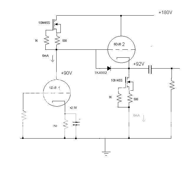
Don't forget to float your heater supply up by about +75V DC. These tubes hate having their cathode-to-heater limits exceeded, especially 5687...
--
Last edited:
Yes, the CCS in the plate presents a very high impedance load to the triode. That makes an almost perfectly horizontal, flat loadline. Distortion is as low as it can be, and gain is as high as it can be. Folks around here use this a lot.
Yes, it's basically the same as using it in the plate. Simplest way to do it is with a single DN2540 or 10M45S depletion mode mosfet. Like this:
Don't forget to float your heater supply up by about +75V DC. These tubes hate having their cathode-to-heater limits exceeded, especially 5687...
--
Great!
Thanks mate, it helped!
Since the cathode of the buffer is at around 150V in respect to ground, I need to elevate the heater supply. I presume 75V should be ok? So it's between the two tubes.
You got it!
I'm pretty sure the maximum heater-to-cathode voltage for these tubes is 100V. With the heaters elevated to +75V, it'll be 75V positive from the first stage cathode, and 75V negative from the second stage cathode. Both within 25V of the limit.
Don't forget the diode from the grid to the cathode of the buffer (second) stage. Without that, the cathode of that stage will be up at the full B+ until the tube warms up and starts conducting. The diode clamps the cathode at the grid potential (ground) until the cathode voltage comes up and 'turns off' the diode. You don't want the cathode up at over +225V from the heater during power-up. Any rectifier diode will do. Most use a 1N4148, but you can use a 1N4001 or whatever. Some use a neon bulb there.
--
Last edited:
Yes, 100V is the limit of Vhk.
Forgot, last question.
How should I use the tubes? One for each channel or one for each role?
Forgot, last question.
How should I use the tubes? One for each channel or one for each role?
I don't think it matters much. I'd say whichever way gets you the neatest layout.
BTW, I did it again... I called this circuit an 'anode follower' when it is actually just a common cathode stage coupled to a cathode follower, with negative feedback from the output to the grid of the input stage.
A true anode follower is basically a common cathode stage with negative feedback taken from its output (after the plate) back to its grid, like so:
That 100k resistor in series with the input grid is the disadvantage of the circuit.
But then again, maybe I could call the circuit we've been talking about a 'buffered anode follower.'
...
Yes, 100V is the limit of Vhk.
Forgot, last question.
How should I use the tubes? One for each channel or one for each role?
One for each role, because it is better for the cathode follower to have a +Voltage on the heater, to avoid hum and heater-cathode breakdown.
One for each role, because it is better for the cathode follower to have a +Voltage on the heater, to avoid hum and heater-cathode breakdown.
Exactly that was what I was thinking about while asking the question 🙂
Having both cathodes from the same tube at the same level vs the heater seemed better to me.
I will come back with the layout.
Don't forget the diode from the grid to the cathode of the buffer (second) stage. Without that, the cathode of that stage will be up at the full B+ until the tube warms up and starts conducting. The diode clamps the cathode at the grid potential (ground) until the cathode voltage comes up and 'turns off' the diode. You don't want the cathode up at over +225V from the heater during power-up. Any rectifier diode will do. Most use a 1N4148, but you can use a 1N4001 or whatever. Some use a neon bulb there.
--
I installed that diode from the beginning in the eagle layout 🙂 Valve Wizard is a really good source.
I would have installed a neon bulb for that retro look but I don't have any, instead plenty of uf4007.
I installed that diode from the beginning in the eagle layout 🙂 Valve Wizard is a really good source.
I would have installed a neon bulb for that retro look but I don't have any, instead plenty of uf4007.
Neon's can be found at any electric supplies shop, they are used inside light switches in dark staircases. They are cheap
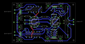
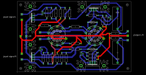
So far I could get to this layout. The untraced links are the ground. Still thinking about how to do it. I presume a start structure with the input PS ground wire in the middle? ** I'm trying to make it without vias, or make the passing from one layer to the other in points where I can solder on both sides. This way I may make it locally for cheap instead of fab houses. Something like this. I highlighted the ground. Anything wrong with it? Should I connect the heatsinks to ground as well? Seems too stuffed, and I want to implement a two-transistor regulator for the buffer tube. So I will move the ccs of the preamp tube plate to the PS board, where I'll add the regulator for the buffer tube. This way it will be less clutter on the tube board.
Attachments
Originally Posted by costis_n View Post
One for each role, because it is better for the cathode follower to have a +Voltage on the heater, to avoid hum and heater-cathode breakdown.
I don't get it. Like I said before, if you have a common heater supply lifted to +75V, the first stage has its cathode at +75V from the heater supply (which is fine) and the second stage has its cathode at -75V from the heater supply (which is also fine). The maximum cathode-to-heater voltage is 100V DC in either direction.
I don't understand why having the first stage cathode at +4V or whatever DC from the heater is better (or even much different) than having that first stage cathode at +75V from the heater. Do I have something to learn here?
--
There was an article* that claimed to show that raising the heater supply +60V above ground reduced coupling from heater-to-cathode and therefore reduced hum at the output. Since the first stage would be prone to hum pickup, it seems raising the heater supply +75V would be a good thing. However, as always, I could be wrong.
* The Valve Wizard has that article as a footnote. Cooper, C. E. (1944). Valve Hum. Electronic Engineering, (July), pp72-5.
--
Last edited:
You are correct. As the article says, ideally we need some voltage above the cathode in the heaters.The first (+75V)is fine, but the ideal for the second stage is ~ +120V. Both stages are dealing with the same signal levels, so they are equally prone to hum pickup, so ideally they both should have their heaters above cathodes. This will need 2 heater windings in the transformer, so it may not happen with off-the-shelf transformers. In a project of mine, I used a separate transformer for the cathode followers heaters.
I hope I explained it well enough.
I hope I explained it well enough.
- Home
- Amplifiers
- Tubes / Valves
- 6n6p preamp. Does it look ok?