Im having a few issues with this SE tube amp im building.
See schematic below:
Main issue is im getting too much mains "hum", the degree of this changes slightly if i play around with the two volume controls.
Im pretty sure its in the preamp stage, and im guessing its due to its high sensitivity preamp stage. When i isolate the preamp from the driver stage, the hum goes away.
Using shielded cable to the grids made no difference in hum.
I also feel i cant get enough control on the gain of the amp, if i crank the volume up full, i can get a reasonable amount of distortion, but i would like more of an overdriven sound when i want it lower, and at the same time, i wouldnt mind being able to make the amp cleaner when i dont want it in overdrive.
Should i move the first volume control over between the first triode and the tone stack perhaps?
Another issue is with only some brands of EL34, the plates on the tube will glow slightly when idle.
I know that single ended amps can draw huge amounts of current when idle, and i suspect this is the issue, i had been advised to increase the cathode resistor to 470 ohms, which i will experiment with, as im confident this will resolve this.
Other than that, im pretty happy with how the amp sounds overall, i just want to make these final tweaks and i should be good to go!
See schematic below:
An externally hosted image should be here but it was not working when we last tested it.
Main issue is im getting too much mains "hum", the degree of this changes slightly if i play around with the two volume controls.
Im pretty sure its in the preamp stage, and im guessing its due to its high sensitivity preamp stage. When i isolate the preamp from the driver stage, the hum goes away.
Using shielded cable to the grids made no difference in hum.
I also feel i cant get enough control on the gain of the amp, if i crank the volume up full, i can get a reasonable amount of distortion, but i would like more of an overdriven sound when i want it lower, and at the same time, i wouldnt mind being able to make the amp cleaner when i dont want it in overdrive.
Should i move the first volume control over between the first triode and the tone stack perhaps?
Another issue is with only some brands of EL34, the plates on the tube will glow slightly when idle.
I know that single ended amps can draw huge amounts of current when idle, and i suspect this is the issue, i had been advised to increase the cathode resistor to 470 ohms, which i will experiment with, as im confident this will resolve this.
Other than that, im pretty happy with how the amp sounds overall, i just want to make these final tweaks and i should be good to go!
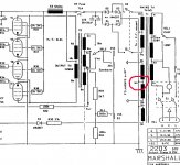
Firstly, I assume those two "1.5" resistors in series with the first two cathodes are actually 1.5k or similar value to make a decent self-bias voltage. If not, try fixing that now.
Not sure why one cathode bypass cap is 50uF and the other 25uF in an otherwise identical circuit. The third stage then has no bypass cap, and the fourth is 25uF. I don't know if a bypass cap on the output is desirable or not - adding the cap increases the gain, but I presume the previous four stages gives plenty, and a bypass cap here surely changes the way the output sounds when it distorts.
Also, the cathode resistor in the third stage is marked 100k, which I'm sure is a much higher value than intended. If that's the real value, this stage is giving a gain of probably less than 1, which would explain the lack of overdrive you describe.
Try shorting the input (the 1M resistor). Does it act the same as far as the hum? I suspect the problem is the actual wiring of the ground connections, which (most) schematics don't show.
Yes they are 1.5K, i should have marked that better sorry 🙂Firstly, I assume those two "1.5" resistors in series with the first two cathodes are actually 1.5k or similar value to make a decent self-bias voltage. If not, try fixing that now.
Yes, i found that odd too, i should have mentioned that ive built this on a design by a local amp builder i knew who died in bed and i never got to ask him any questions, i have his exact amp (that was plagued with issues) that i have had to iron out and i redesigned the tone stack etc.Not sure why one cathode bypass cap is 50uF and the other 25uF in an otherwise identical circuit. The third stage then has no bypass cap, and the fourth is 25uF. I don't know if a bypass cap on the output is desirable or not - adding the cap increases the gain, but I presume the previous four stages gives plenty, and a bypass cap here surely changes the way the output sounds when it distorts.
Ive never really seen bypass caps on the cathode of the driver stage before.
I know with marshall amps, most pretty much only have a cathode bypass cap on the cathode of the first preamp stage.
TBH, i think that 25uf, let alone 50uf is rather high, some guitar amps are like this, so i left it for the time being, but they are something I have wondered about.
Also, the cathode resistor in the third stage is marked 100k, which I'm sure is a much higher value than intended. If that's the real value, this stage is giving a gain of probably less than 1, which would explain the lack of overdrive you describe.
OK, ill look at that, perhaps i will lower it to 47K, i actually lowered both the anode resistors to 47K, because both of them were 100K and i was not getting very much output drive.
Try shorting the input (the 1M resistor). Does it act the same as far as the hum? I suspect the problem is the actual wiring of the ground connections, which (most) schematics don't show.
Ok, i will try that, im pretty sure 1M to ground is common with alot of amps, particularly with fender, but its worth a shot, im aware of ground loops, and have earthed each cathode to ground on a busbar like what Marshall do on their amps.
Your input doesn't have a grounding shunt. Plug your guitar in but turn its volume control to zero. Hum still?
Hum can come from many sources, and each has its own cure.
First make sure whether it is 50Hz or 100Hz hum.
Don't just play with the volume controls, turn one all the way down, does it kill the hum? Back up and turn the other one all the way down, hum killer?
You may or may not have this issue, but it appears you are taking the power tube plate supply right from the first filter node. Single ended amps cannot cancel supply ripple like push pull amps. So an extra RC or LC ahead of that might help power stag ehum.
Your input doesn't have a grounding shunt. Plug your guitar in but turn its volume control to zero. Hum still?
Hum can come from many sources, and each has its own cure.
First make sure whether it is 50Hz or 100Hz hum.
Don't just play with the volume controls, turn one all the way down, does it kill the hum? Back up and turn the other one all the way down, hum killer?
You may or may not have this issue, but it appears you are taking the power tube plate supply right from the first filter node. Single ended amps cannot cancel supply ripple like push pull amps. So an extra RC or LC ahead of that might help power stag ehum.
Definitely 50hz hum. Hum is present with volume down all the way, but will drop slightly.
Still hums with the guitar turned down also.
Pretty sure all the hum is picked up in the preamp stage, no hum if i isolate the preamp from the driver tube.
This calculator is useful for the cathode bypass caps, i think they are way off with the values used, but would that affect the hum?
https://www.ampbooks.com/mobile/amplifier-calculators/cathode-capacitor/calculator/
Im thinking of using between 0.68 and 1uf on the first stage. IDK if i even need one on the second stage or not.
Last edited:
100Hz hum would be power supply ripple, so 50Hz means it is elsewhere. And there are oh so many elsewhere it could be. Grounding issues, heater influences. etc.
"Isolate the preamp" is not very specific, how did you do that? Does pulling the first tube kill the hum? Or only pulling the second?
Selective grounding can work. If there is no DC involved, you can ground a clip wire and then with the free end, ground off the signal path at various points. The four triode grids for example. Step along and see where the hum is and is not.
Don't worry about the bypass caps until you have fixed everything else - they won't fix the hum by themselves.
Show us the schematic of your power supply. And a photo of the guts of the amp.
For any gain questions we need to see the anode and cathode voltages of each stage.
Is the heater supply DC or AC?
If AC does it have a centre tap to ground (or the cathode of the power tube)?
Cheers
JimG
Show us the schematic of your power supply. And a photo of the guts of the amp.
For any gain questions we need to see the anode and cathode voltages of each stage.
Is the heater supply DC or AC?
If AC does it have a centre tap to ground (or the cathode of the power tube)?
Cheers
JimG
100Hz hum would be power supply ripple, so 50Hz means it is elsewhere. And there are oh so many elsewhere it could be. Grounding issues, heater influences. etc.
"Isolate the preamp" is not very specific, how did you do that? Does pulling the first tube kill the hum? Or only pulling the second?
Selective grounding can work. If there is no DC involved, you can ground a clip wire and then with the free end, ground off the signal path at various points. The four triode grids for example. Step along and see where the hum is and is not.
I am quite familiar with what 50hz sounds like (we are 50hz in New Zealand), its the same sound you get on any guitar amp when you touch the end of your instrument lead that is connected to the amp, and thats what i am hearing with this.
There are lots of things that could be producing the noise, like power cables, transformers, etc. The thing with power noise, is that it is everywhere around you, or else touching the lead would do nothing.
I thought i laid out my chassis rather well though and keep the wires twisted and away from the preamp section as far as possible.
When i say i isolated the preamp, yes i pulled out the first tube from the driver stage (only one preamp tube in this amp)
Don't worry about the bypass caps until you have fixed everything else - they won't fix the hum by themselves.
Show us the schematic of your power supply. And a photo of the guts of the amp.
For any gain questions we need to see the anode and cathode voltages of each stage.
Is the heater supply DC or AC?
If AC does it have a centre tap to ground (or the cathode of the power tube)?
Cheers
JimG
OK, good idea, i should address the hum first.
Pretty sure its not heater hum, no centre tap, it is AC.
Half the power supply is drawn in the above schematic, only thing that is not shown is the transformer and tube rectifier.
Im using a 5U4, but will swap over to a GZ34 when i find one.
Basically its a centre tapped to ground full wave rectifier. The cathode is going straight to the first filter cap and choke in my schematic.
Hope this helps, but ill grab some photos soon.
Here are the photos:
Ive been protoyping, and have tacked on different components etc, i will tidy that up later, but i had the hum before changing any of that.
Ive been protoyping, and have tacked on different components etc, i will tidy that up later, but i had the hum before changing any of that.
An externally hosted image should be here but it was not working when we last tested it.
An externally hosted image should be here but it was not working when we last tested it.
An externally hosted image should be here but it was not working when we last tested it.
This is what I was trying to say by (temporarily) "shorting the 1M resistor" - it helps diagnose where the problem is.Your input doesn't have a grounding shunt. Plug your guitar in but turn its volume control to zero. Hum still?
...
Pretty sure its not heater hum, no centre tap, it is AC.
...
Is the AC heater supply 'floating'? (That can create a lot of hum.) If there is no centre tap, you can create an artificial one and then ground it, or even better 'elevate' the artificial centre tap to some DC level.
There's a good description and explanation of the various options here:
The Valve Wizard
If the heater supply is floating at present, you can try grounding it temporarily (at one point only) to see if that reduces the hum. If that does work, even better results will be obtained by the 'artificial centre-tap' plus 'DC elevation'.
Last edited:
Malcolm sums up the heater issue better than I would have. A lack of heater ground reference is begging for hum.
50Hz is indeed what you hear when you touch the cord tip, but 100Hz is one octave higher and sounds very similar. it will be the same note, but a bit more "treble-y". If pulling the first tube kills the hum, then likely 100Hz is not the issue.
Hum is indeed all around you, but it gets into amps many ways, and each way has its own cure. Shielding won't help grounding hum, and grounding changes won't help where shielded cable is needed.
OK, ill try grounding one side of the heater windings and get back. I didnt think much about a center tap on the heaters. Im pretty sure my marshall 2203 clone i built doesnt have one on its heater supply, there is a very faint hum present from the heaters on that amp, but its very quiet, you have to crank it up quite a bit to hear it.
OK, ill try grounding one side of the heater windings and get back. I didnt think much about a center tap on the heaters. Im pretty sure my marshall 2203 clone i built doesnt have one on its heater supply, there is a very faint hum present from the heaters on that amp, but its very quiet, you have to crank it up quite a bit to hear it.
Your post:
caught my eye, as I'm not very familiar with Marshall designs. (I notice you edited the post to make it clear that you were talking about a clone of a Marshall - that makes a lot of sense.)***************
OK, ill try grounding one side of the heater windings and get back. I didnt think much about a center tap on the heaters. (Im pretty sure my marshall 2203 doesnt have one on its heater supply)
***************
You may have already checked the Marshall schematic? The CT is shown, though those Brit-style schematics are a bit unclear sometimes. In some amps the heater ground is hard to spot, especially in cases where there's no CT and there are just a couple of 100 ohm resistors tacked to ground at one of the tube sockets.
Attachments
And to be honest, it really doesn't matter what some other amp you built did. getting away with a poor grounding scheme in one amp is no guarantee it will be that way elsewhere. Every amp is an individual.
Your post:
caught my eye, as I'm not very familiar with Marshall designs. (I notice you edited the post to make it clear that you were talking about a clone of a Marshall - that makes a lot of sense.)
You may have already checked the Marshall schematic? The CT is shown, though those Brit-style schematics are a bit unclear sometimes. In some amps the heater ground is hard to spot, especially in cases where there's no CT and there are just a couple of 100 ohm resistors tacked to ground at one of the tube sockets.
OK, this is a little embarrassing, as i checked it and do remember now that it did indeed have a centre tap on the heater supply! lol
Anyway, that schematic is quite different to my amp, mine was a 1970's JMP 100W master lead 2203 model, which i think has some differences between the later JCM series amps.
AFAIK, they never had 100 ohm resistors to ground.
Anyway, i wired one side of the heater supply to ground and the humming goes that i had when the volume was turned town!
I do still get some hum when i turn up the volume higher, and this gets more intense as i turn it up, but i expect this is the norm as the amp goes into overdrive.
Of course, less hum is desirable, and ive noticed that i get a totally different sound now, its like a trickling or chattering sound that comes and goes with the hum that remains, you only really hear it when the volume is about half way up or more.
I will have to record the sound of it if no one has any idea what it is.
Do those volume controls look OK the way i have them laid out on the schematic?
I was wondering if i would have better control between the first triode and the tone stack?
Either way, ive made some progress, which is good, ill read up what is written on the valve wizard link anyway. I dont know what options i have with no CT on the heater supply.
I could go DC i guess?
Last edited:
I dont know what options i have with no CT on the heater supply.
Make an artificial one with two 100 ohm resistors.
Make an artificial one with two 100 ohm resistors.
I agree.
Once you have that 'artificial center tap' for your heaters, you can experiment with where you'll connect it.
Possibilities are a ground point or an elevated voltage reference point (power tube cathode or a voltage divider across the HV somewhere).
About the 'other noise' you are getting as you turn the volume up:
Does the output volume (guitar sound) keep going up as you advance the volume/gain control, or does the amp 'not get any louder' or even 'get quiet' at some point? I'm thinking about possible oscillation (mostly way beyond hearing frequencies). The reason this comes to my mind is that I've been struggling to tame oscillation in an amp project - there's not a lot of audible evidence, but the scope shows what's happening.
Without a scope, you could try moving wires around (with a stick) to see if anything makes the noises change.
- Status
- Not open for further replies.
- Home
- Live Sound
- Instruments and Amps
- Issues with Single ended guitar amp build