As I proved with my stupid comment earlier, input jack wiring is something that I seem to find confusing!🙁I was thinking of doing something similar and wire both resistors as gridstoppers together on the valve socket and connect with shielded cable to the jacks.
Ive already got a hole in the chassis with a jack installed, so i may as well use it .
............
Ahh, yes your right, that is how the fenders are configured.
Would say using a 4.7K grid stopper be a better idea and then wire both input jacks in a similar fashion to a fender amp?
I probably would stay with 56K instead of 68K
I need to keep going back to one of the simpler shematics for reference (see attached image).
I think either of your choices sound OK- the decision may depend on layout and space available, wiring points near the tube socket, etc. Grid stoppers are one of the few places where I break the 'every component anchored at both ends' rule as I often put the resistor at the end of the connecting wire (shielded or not) with heat shrink over, soldered to the tube pin with as little lead as possible.
Attachments
I also see some amps appear to have a low pass filter with a 470pf cap across a 470K resistor that is in series with the grid and input, do these serve as a noise suppressor?
I see other configurations with caps across the input to ground, but not sure what purpose these serve, as i found i got more noise adding them.
Can you remember specific examples from schematics?
Usually caps across the input are to prevent RF noise, I think.
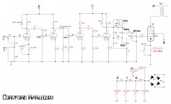
I also see caps in parallel with the plate resistor, which I understand is an 'oscillation tamer' in some designs.
Here's an example of the latter, which also shows separate grid stopper and input resistors (Cornford Harlequin).
Attachments
I also see some amps appear to have a low pass filter with a 470pf cap across a 470K resistor that is in series with the grid and input, do these serve as a noise suppressor?
Was that the Kendrick Roughneck amp?
I think the idea there is to allow the higher (audio) frequencies to bypass the 470k resistor to give a 'bright' input - that's what the labels seem to imply.
I'd be curious to see comments on this from more expert builders like Malcolm.
Attachments
As I proved with my stupid comment earlier, input jack wiring is something that I seem to find confusing!🙁
I need to keep going back to one of the simpler shematics for reference (see attached image).
I think either of your choices sound OK- the decision may depend on layout and space available, wiring points near the tube socket, etc. Grid stoppers are one of the few places where I break the 'every component anchored at both ends' rule as I often put the resistor at the end of the connecting wire (shielded or not) with heat shrink over, soldered to the tube pin with as little lead as possible.
Thats what i remember in that schematic you have!
IDK why fender dont use gridstoppers there?
Alot of amps i see only have a gridstopper on the first stage anyway, and i guess thats because thats where most of the noise is picked up in.
Interesting that fender dont use one in that position, but TBH i have not noticed any audible difference with or without them on the other stages of my amp, so ill probably remove them to make it tidier.
Ill still keep a gridstopper on the first stage I think anyway.
Can you remember specific examples from schematics?
Usually caps across the input are to prevent RF noise, I think.
I also see caps in parallel with the plate resistor, which I understand is an 'oscillation tamer' in some designs.
Here's an example of the latter, which also shows separate grid stopper and input resistors (Cornford Harlequin).
I saw this on my mates 65 amps SOHO, you wont find any schematic for it anywhere though. I want to study the amp's design further when i get a chance, its a really nice amp.
As far as it goes with what i described with a 470p resistor across a 470K resistor, the Marshall 2203 has this directly from the low input jack into the grid of the second gain stage.
Last edited:
The Kendrick Roughneck input circuit is interesting. If you removed the 250pF cap then both inputs would work the same: a potential divider with two 470k resistors, putting half the input signal voltage onto the grid.
But with the 250pF in place, the ‘bright’ input favours the high frequencies, putting more than half of their voltage on to the grid, while the 'mellow' input reduces the high frequencies by putting less than half of their voltage onto the grid.
But with the 250pF in place, the ‘bright’ input favours the high frequencies, putting more than half of their voltage on to the grid, while the 'mellow' input reduces the high frequencies by putting less than half of their voltage onto the grid.
The Kendrick Roughneck input circuit is interesting. If you removed the 250pF cap then both inputs would work the same: a potential divider with two 470k resistors, putting half the input signal voltage onto the grid.
But with the 250pF in place, the ‘bright’ input favours the high frequencies, putting more than half of their voltage on to the grid, while the 'mellow' input reduces the high frequencies by putting less than half of their voltage onto the grid.
Very interesting.
I may play around a bit when i get a chance.
Only thing is really that you can spend hours swapping components back and forth to try and find would you like the sound of! lol
All very fine to use computer models and calculations, but i find with audio, especially guitar, you have to find what sounds best, and each ear is different too!
IDK why fender dont use gridstoppers there?
Alot of amps i see only have a gridstopper on the first stage anyway, and i guess thats because thats where most of the noise is picked up in.
Interesting that fender dont use one in that position, but TBH i have not noticed any audible difference with or without them on the other stages of my amp, so ill probably remove them to make it tidier.
Ill still keep a gridstopper on the first stage I think anyway.
.
Fender didn't use any part they could omit. The goal was profit, not engineering.
You aren't meant to hear grid stoppers (normally). Leaving them out is like taking out your seat belts cos you didn't have an accident last time you drove.
The advantage of DIY is being able to include good engineering principles and not try and save every dollar possible.
I have had another look at your original schematic - there is no bypass cap on the power valve. You could easily try one and see if it helps get the sound you want.
Reducing 1 or more of your coupling caps may help the mud - I tend not to use anything bigger than 0.01u, and you could try going as low as 2n.
This circuit still has a lot of potential for improvement.
Have fun
JimG
Last edited:
OK, that makes sense, i didnt think much about a bypass cap on the power tube, i usually only see that in Hifi systems.Fender didn't use any part they could omit. The goal was profit, not engineering.
You aren't meant to hear grid stoppers (normally). Leaving them out is like taking out your seat belts cos you didn't have an accident last time you drove.
The advantage of DIY is being able to include good engineering principles and not try and save every dollar possible.
I have had another look at your original schematic - there is no bypass cap on the power valve. You could easily try one and see if it helps get the sound you want.
Reducing 1 or more of your coupling caps may help the mud - I tend not to use anything bigger than 0.01u, and you could try going as low as 2n.
This circuit still has a lot of potential for improvement.
Have fun
JimG
Should i be taking negative feedback from the OT into the driver stage?
That cleans it up but lowers the output typically.
Interesting about the coupling caps, i could try some 4.7nf caps i have floating around somewhere.
Dont know why 0.022 is so popular though.
OK, that makes sense, i didnt think much about a bypass cap on the power tube, i usually only see that in Hifi systems.
I agree with Jim's recommendation about the bypass cap on the output tube.
It's a feature of a lot of guitar amps (5F1 Champ, 5E3 Deluxe, 6G10 Harvard, Marshall 18Watt and on and on), and definitely increases the 'loudness' and changes the tone.
It's a simple mod (a 25volt 25uF electrolytic will give you the idea), and it can be made switchable if you want to make comparing the effect (with and without the bypass cap) easier.
Attachments
Switches are great - especially for before and after while deciding on final values and design.
You could try feedback from the OT. My amps often have a 3 way switch for this aiming for different levels eg a lot (fender), a little (Marshall ), none (Vox)
You could try feedback from the OT. My amps often have a 3 way switch for this aiming for different levels eg a lot (fender), a little (Marshall ), none (Vox)
I agree with Jim's recommendation about the bypass cap on the output tube.
It's a feature of a lot of guitar amps (5F1 Champ, 5E3 Deluxe, 6G10 Harvard, Marshall 18Watt and on and on), and definitely increases the 'loudness' and changes the tone.
It's a simple mod (a 25volt 25uF electrolytic will give you the idea), and it can be made switchable if you want to make comparing the effect (with and without the bypass cap) easier.
That looks interesting indeed, i probably will give this a try and i could always add a switch as you say.
In my case, would it be as simple as putting a 25uF cap across the cathode resistor?
Another thing i was going to ask was if i need a heavy wirewound resistor on the cathode.
I could make the wiring much more tidy if i could get away with a 1W carbon film.
... I could make the wiring much more tidy if i could get away with a 1W carbon film.
You can measure the quiescent voltage across your cathode resistor and use the formula P = (V x V / R) to find the power dissipated in that resistor. Then double that (to give a good safety factor) to check the power rating of the resistor.
Last edited:
That looks interesting indeed, i probably will give this a try and i could always add a switch as you say.
In my case, would it be as simple as putting a 25uF cap across the cathode resistor?
Yes - since it will be an electrolytic, observe polarity (- to ground) and that will do it.
I usually use a 50v-rated axial cap there (they are so small and cheap nowadays) but you can measure the voltage across the resistor (which you'll be doing anyhow to figure your cathode resistor power dissipation) and probably get away with a 25v cap if that's all you have in your parts bin.
Yes i think i might have some 25v around, although most are rated at 50v and alot larger.
I like to keep lead lengths short if possible, but the size of the caps and large cathode resistors make it hard to ground to the lug due to the gap being narrower than the components.
It would be alot tidier if i utilised the spare turrets on the PTP board for wiring it to the cathode, since its the power stage am i likley to pick up any noise, or is it better to keep the shortest possible path to ground?
Last edited:
It would be a lot tidier if i utilised the spare turrets on the PTP board for wiring it to the cathode, since its the power stage am i likely to pick up any noise, or is it better to keep the shortest possible path to ground?
Most of the commercial 'boutique' amp builders seem to get away with almost everything on a turret or eyelet board so you should be OK doing the same. Try it and see.
I'm not very 'lucky' - my last build was a Cornford clone which had a lot of gain and I had problems with oscillation, so I ended up moving everything off of boards and on to a pretty tight P2P scheme.
After I got my clone working, I came across a YouTube video which showed the guts of a Cornford and it was turret board and wires strung all over. Obviously the experts know where the rules can be broken and where they must be observed!🙂
lol, quite possibly, or else pure luck.
Some boutique amps such as 65amps are the opposite, ive seen pretty much all the wiring using shielded cable!
Ive just done some more work on the amp and added a cathode bypass cap on the output tube.
Im getting about 25v when idle and just over 30v when playing at full blast.
The resistor is getting extremely hot to touch, its rated at 5W, but my calculations at 330ohm work out to only 2.7W, which is not alot.
Anyway, i placed a 25uf cap across the resistor and it gives way too much gain, it makes it louder, but at the same time, very overdriven, hard to run clean. Would also oscillate and whistle when you turn up to half volume or more.
I put a 2.2uf across, and this made some improvement, but will still oscillate if turned up enough.
I probably only need 0.47uf or 1uf across it perhaps?
Im yet to increase the resistor to 470 ohms, this may also help.
2.7W @25 volts is over 100mA - or is my math wrong?I
The resistor is getting extremely hot to touch, its rated at 5W, but my calculations at 330ohm work out to only 2.7W, which is not a lot.
What's the power dissipation for your tube at 100mA?
Also, I'd be thinking about 'turning down' the preamp gain as one possibility for taming the oscillation, after lead dress and grid/screen/plate stoppers and 'the usual suspects' were tried.
2.7W @25 volts is over 100mA - or is my math wrong?
What's the power dissipation for your tube at 100mA?
Also, I'd be thinking about 'turning down' the preamp gain as one possibility for taming the oscillation, after lead dress and grid/screen/plate stoppers and 'the usual suspects' were tried.
The maximum voltage i measured across the cathode resistor was 30v so I worked out 30V / 330 ohms = 0.09A, which is close to 100mA like you said.
0.09A x 30V = 2.7W is this correct? At 100mA it should only be 2.5W according to my calculations.
It doesnt go below 25v when idle even with no signal going through with volume down, so 100 mA is probably the maximum current on the cathode resistor.
Adding the cathode bypass cap has increased the gain significantly and i kind of was expecting the oscillation with how loud it was at only a moderate volume. Only issue is it makes it sound more overdriven and less clean, infact its dont the opposite of what i expected, as i was expecting it to sound cleaner while louder at the same time. I have not scoped it yet, but i expect there will be significant clipping.
Anyway, i have not measured the output of the amp yet, but i expect i am probably getting 15W RMS from it.
Im not sure what the power dissipation is of the output tube when idle.
I usually just put a tone through the amp and measure the RMS output in watts, which is probably a good 15W.
- Status
- Not open for further replies.
- Home
- Live Sound
- Instruments and Amps
- Issues with Single ended guitar amp build