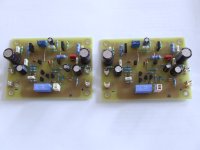
I etched a pair. I'll try to get it populated and tested tomorrow.
Nice pcb
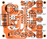
Yes, it's stereo.
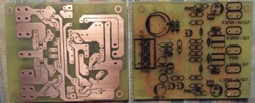
Schematic from mister Mile http://www.diyaudio.com/forums/soli...imate-fidelity-amplifier-550.html#post4518802
Sprint layout file for own customizations attached
Oh, i see now i skipped 100K resistor from 5551 colector to +, sorry about that
Hi c08bm,
Great Layout!!🙂 I will correct mine based on your layout.
reg
prasi
Hi
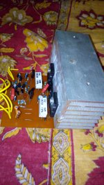
I completed building the AX-14 amplifier and i am getting 4vdc output on AX14 what could be wrong with it
My voltage is +/-20vdc.
please tell what is wrong
Connect input gnd to psu gnd...
You can use this simple PSU
Thank you for the reply sir...
I changed the values of few components. PCB design is original Anistardi's. This is the best version of AX11. Highly recommended!
Congratulation. 😎
Can you share the components that you changed?
How about sound impression?
Can you share the pcb also?Congratulation. 😎
Can you share the components that you changed?
How about sound impression?
Connect input gnd to psu gnd...
Thanks Sir for replying. Now it is give around 20mV
But there is a sound problem it cannot play anything clear i also tried adjusting the bias still the same
please what could be the problem please see image?
Attachments
Congratulation. 😎
Can you share the components that you changed?
How about sound impression?[/QUOTE
I slightly lowered the current through VAS transistors (R12, R16), using 68R instead of 47R.
R1 = 750R
C2 = 220pF
R22, R23 = 0R33
I am short of time at the moment so I shall share subjective impressions later.🙂
Thanks Sir for replying. Now it is give around 20mV
But there is a sound problem it cannot play anything clear i also tried adjusting the bias still the same
please what could be the problem please see image?
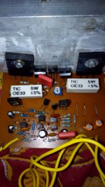
My AX-14 update:
Just checked again everything works fine for the low frequency but for high frequency is sounding so slow.
please tell me what to change i want to use this amp for high frequency.
Last edited:
My AX-14 update:
Just checked again everything works fine for the low frequency but for high frequency is sounding so slow.
please tell me what to change i want to use this amp for high frequency.
What is the value of capacitors you used for C10 and C9? If you used 100pF, you can lower to 22pF - 47pF.
Last edited:
Congratulation. 😎
Can you share the components that you changed?
How about sound impression?[/QUOTE
I slightly lowered the current through VAS transistors (R12, R16), using 68R instead of 47R.
R1 = 750R
C2 = 220pF
R22, R23 = 0R33
I am short of time at the moment so I shall share subjective impressions later.🙂
Thanks Mr. Evanlukic,
I am going to test this Bimo version too. I made my own layout posted in http://www.diyaudio.com/forums/soli...imate-fidelity-amplifier-541.html#post4460302. I will update it with your tested values.
Reg
Prasi
Can you guys please include the post # when linking. The links don't always work, at least not on my computer.
Yes, it's stereo.
Schematic from mister Mile http://www.diyaudio.com/forums/soli...imate-fidelity-amplifier-550.html#post4518802
Sprint layout file for own customizations attached
Oh, i see now i skipped 100K resistor from 5551 colector to +, sorry about that
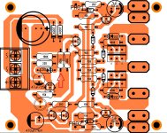
I etched a couple boards per your sprint file. After completing them I decided to add some text to note the use of the terminals for clarity later. Alignment is not perfect because I added it after the fact. I also added a little copper at the ground trace at the bottom. It was very thin where it passed the "Pro" connection. I will try to populate them today if I have time.
Blessings, Terry
Attachments
Can you guys please include the post # when linking. The links don't always work, at least not on my computer.
Sorry, the post is #5402 (my layout). Bimo's updated schematic (on which my layout is based) is at #5221. Bimo's original layout is at #5214😀
reg
Prasi
Sorry, the post is #5402 (my layout). Bimo's updated schematic (on which my layout is based) is at #5221. Bimo's original layout is at #5214😀
reg
Prasi
Thanks.
After etching I noticed a missing resistor. I added it to the sprint file and will just fit it in on the pcb I already etched. Let me know if I am right about this.
Thanks, Terry
Attachments
Last edited:
Thanks.
After etching I noticed a missing resistor. I added it to the sprint file and will just fit it in on the pcb I already etched. Let me know if I am right about this.
Thanks, Terry
Terry if these layout is correct can you share the black and whit with us
If is possible in a PDF file to.
Thank you very much
Greetings gabor
- Home
- Amplifiers
- Solid State
- 100W Ultimate Fidelity Amplifier