I know you use the Toshiba's in the F5TV3 like I do. Are you using the IRF's in the F6? Perhaps that's the reason?
Do you have any problem driving the F6 with its 14db gain with a DCB1?
You may wish to consider building a transformer or auto former based passive to use. Really gives a very natural sound with my F5TV3.
Nash
Yes in the F6 I used IRFP240's from a 1,40 euro a piece 😛
I have Semisouth R100's but do want to use them in J2 clone, if I ever get the schematics 😉
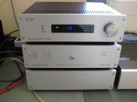
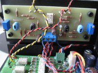
Indeed the 14 dB is often a problem with DCB1, but I have a 10-12 dB Juma gain stage which I can switch in with just one switch. See pictures.
Attachments
Walter, thats nice review and you just saved me. I was going to put F6 on my next build after AJ, but now i'l just wait for papa vfet2 kit to be released.
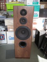
Btw what is your loudspeaker?
haha, sure you have to build an Aleph J 🙂
After that the VFET part 1 or 2.
Speakers are big, home made: 4 ohm, 90db/W/m
Attachments
Walter
Was your F6 built with the diy store board?
Best
Bob
Yes, DIY audio store boards, which have the problem of the wrongly connected capacitor to the source resistor...
Maybe that will alter the sound of the F6 if I correct it. I saw first reactions from others saying it does....
All my F6 iterations were either P to P (R100s), Tea Bag boards(IRF240s) or buzzforbs Funny6 (SUSY with R100s).I used Onetics transformers with each. I am currently putting together a VFET2 to compare. In my system and to my ears the F6 remained after listening to a M2, a Aleph 30, a Aleph J and a Aleph Jango. I do have a F3 that I really like and F4s set up for headphones.Again my ears and my system. his is an experimenter's heaven.
Hi Walter,
Really nice work!
What bias is your Aleph J running at?
Cheers,
Dennis
Sent from my Z220 using Tapatalk
Really nice work!
What bias is your Aleph J running at?
Cheers,
Dennis
Sent from my Z220 using Tapatalk
All my F6 iterations were either P to P (R100s), Tea Bag boards(IRF240s) or buzzforbs Funny6 (SUSY with R100s).I used Onetics transformers with each. I am currently putting together a VFET2 to compare. In my system and to my ears the F6 remained after listening to a M2, a Aleph 30, a Aleph J and a Aleph Jango. I do have a F3 that I really like and F4s set up for headphones.Again my ears and my system. his is an experimenter's heaven.
This from a guy who runs a cyclotron.
😎
The F6 is an amazing amp. I have dipped into SET tube amplifiers of late and have built 2 SET's. The last is a very good SET amplifier and it is very very hard to distinguish between the SET and my F6. I will play the F6 and think this is great and might be better than the SET, then I will do the opposite and play the SET and think the same thing. If I were to walk into the room without knowing which is playing I do not believe I could pick the one playing. If the goal is to design a SS amp that sounds like a SET the F6 is very very close. There are differences in the sound but the differences are very subtle. Now my observations are with my horn speakers in my room so your observations may be different. I have plans to build one of the V-fet amplifiers and I have much anticipation to hear how great it is.
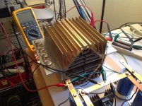
I finally got around to testing my VFETs. Four each of the 2SK82 and 2SJ28, not many. I tested at 1.5 amps, 25Vds
2SK82
#1 7.2 Vgs
#2 7.8 Vgs
#3 7.4 Vgs
#4 7.0 Vgs
Not bad, happy with that spread
2SJ82
#1 11.4 Vgs
#2 11.1 Vgs
#3 8.9 Vgs
#4 8.5 Vgs
Two groups that will work.
The 11 Vgs ones will be problematic in the CSX boards with out changing some values on the regulators. By the time I got the voltages to 11 volts the regulator wasnt working with the 15 volt supply. The 431 needs a mA to work and the voltage divider will take another mA, that is 2mA going through the 3.3K ohm supply resister, resulting in a 6+ volt drop. 15v-6v leaves only 11 volts left over for the regulator. In testing the ref. on the regualtor was decreasing at that point, thus no regulation. If I were to use the 11 Vgs VFETs I think a 1K ohm supply resistor and a 10K ohm instead of 7.5K ohm in the voltage divider would work. The other fix would be to start with a higher supply voltage, but in my case I already have the stock 12VAC transformers.
If your Vgs values are in between I would check and make sure your regulator is working by measureing the 2.5 volt reference. You want a regulator and not just a voltage divider.
My test setup used a separate voltage ref, not the CSX boards. Then I tested the voltages from the CSX boards.
BDP
Attachments
Last edited:
I have Semisouth R100's but do want to use them in J2 clone, if I ever get the schematics 😉
I'll probably get around to publishing a J2 clone at some stage, based on what I have learnt from Papa (maybe not a perfect clone but definitely in the ball park). Zen Mod published one a few years ago now. I'm not sure what his feelings are about sharing it, I know he wouldn't share it publicly at least.
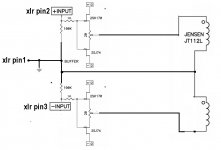
I have a CSX2 question that I hope is simple. Is it possible to drive the input transformer with two buffers, once for each input phase? The wiper of two pots would be connected to the In+ and In- of the original schematic. A second small bipolar supply would be used to insolate the transformer as intended.
I finally got around to testing my VFETs. Four each of the 2SK82 and 2SJ28, not many. I tested at 1.5 amps, 25Vds
2SK82
#1 7.2 Vgs
#2 7.8 Vgs
#3 7.4 Vgs
#4 7.0 Vgs
Not bad, happy with that spread
2SJ82
#1 11.4 Vgs
#2 11.1 Vgs
#3 8.9 Vgs
#4 8.5 Vgs
Two groups that will work.
The 11 Vgs ones will be problematic in the CSX boards with out changing some values on the regulators. By the time I got the voltages to 11 volts the regulator wasnt working with the 15 volt supply. The 431 needs a mA to work and the voltage divider will take another mA, that is 2mA going through the 3.3K ohm supply resister, resulting in a 6+ volt drop. 15v-6v leaves only 11 volts left over for the regulator. In testing the ref. on the regualtor was decreasing at that point, thus no regulation. If I were to use the 11 Vgs VFETs I think a 1K ohm supply resistor and a 10K ohm instead of 7.5K ohm in the voltage divider would work. The other fix would be to start with a higher supply voltage, but in my case I already have the stock 12VAC transformers.
If your Vgs values are in between I would check and make sure your regulator is working by measureing the 2.5 volt reference. You want a regulator and not just a voltage divider.
My test setup used a separate voltage ref, not the CSX boards. Then I tested the voltages from the CSX boards.
BDP
Good point about the regulators.... I have measured 16 x 2SJ28 and they spread from 4.9V to 11.9 Volt Vgs at 1.5A at 24V
I have a CSX2 question that I hope is simple. Is it possible to drive the input transformer with two buffers, once for each input phase? The wiper of two pots would be connected to the In+ and In- of the original schematic. A second small bipolar supply would be used to insolate the transformer as intended.
I think you mean this buffer, twice?
Attachments
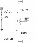
Yes, exactly. Would that work? I don't need a buffer but if I did, I wouldn't really want to lose the balanced input.
Don't know if it will work.
I think it will, but I always have trouble with figuring out how the 'audio ground' will fit in... You are going to use separate PSUs for the buffer so that may help.
I think it will, but I always have trouble with figuring out how the 'audio ground' will fit in... You are going to use separate PSUs for the buffer so that may help.
Thanks! The article states:
"You also have the option of running the input windings of the transformer in series, sacrificing 6 dB of gain, but doubling the input impedance and halving the capacitance."
So, if the connection from pin 1 to the center of the two windings is omitted, would the above also be true?
"You also have the option of running the input windings of the transformer in series, sacrificing 6 dB of gain, but doubling the input impedance and halving the capacitance."
So, if the connection from pin 1 to the center of the two windings is omitted, would the above also be true?
Is easy in use only a couple of complementary like the original buffer unbound the gates and connecting them to the differential input with a 100k to ground.
- Status
- Not open for further replies.
- Home
- Amplifiers
- Pass Labs
- Article - Sony VFETs part 1