I have measured the real inductance values of the Jensen if you want them for
Spice.....?
That would be nice.
😉

Version 0.1.
Now I understrand the feeling that ZM mentioned in his blog...a dog waiting for a bone. 😀😀
Thank you 2 picoDumbs, Chul
Hockey Puck Version 0.1
Notes:
1) Resistor-Trimpot combination (R12 + 25 Turn 5k Trim Pot) is setup for fine adjustment around the 4.7V figure in Nelson's schematic. These devices need fine adjustment. Set trim pot to midpoint to start the adjustment procedure.
2) Output devices are models I had access to, similar to Nelson's choice of Hockey Pucks, with these devices in this circuit the voltage reference needs to be at a different value with bias of 3A that this circuit produces with those models. Don't get confused with this
Last edited:
Notes:
1) Resistor-Trimpot combination (R12 + 25 Turn 5k Trim Pot) is setup for fine adjustment around the 4.7V figure in Nelson's schematic. These devices need fine adjustment. Set trim pot to midpoint to start the adjustment procedure.
2) Output devices are models I had access to, similar to Nelson's choice of Hockey Pucks, with these devices in this circuit the voltage reference needs to be at a different value with bias of 3A that this circuit produces with those models. Don't get confused with this
I got the bone in my mouth, what are you talking about? 😀😀
I would like to try the supply between 40V~60V. I hope the resistor value in your circuit can cover these for about 3A bias, or around that current. I am not trying to fix things for my wife to turn on and enjoy music.
A power supply with CC and CV will make this easy but mine cannot cover more than 3A...
I setup the voltage reference for IXFN140N20P which Nelson says is around 4.7V. So if you have those devices you are good to go.
What supply voltage will you be using?
You adjust the trimpot till the voltage between the 2 x 0.2V resistors at output measure half the supply voltage.
For a 60V supply you want 30V.
For a wider range of possible adjustments have both 10k and 15k available for R12. If you need less than 4.1V on the voltage reference to get half supply voltage between R1 and R2 then insert 15k at R12.
For R13 I would use CMF60 or equivalent
For a 60V supply you want 30V.
For a wider range of possible adjustments have both 10k and 15k available for R12. If you need less than 4.1V on the voltage reference to get half supply voltage between R1 and R2 then insert 15k at R12.
For R13 I would use CMF60 or equivalent
Last edited:
I setup the voltage reference for IXFN140N20P which Nelson says is around 4.7V. So if you have those devices you are good to go.
What supply voltage will you be using?
Thank you for all this help.
I have two 48V 16A SMPS which can be adjusted 38~58V. If I use FET filter then it will be 54V max. This will be the one I will try first. I also have this DC DC converter that can make up to 90V if I want. So voltage wise I have things to play with, If I ignore the possible ripple..
50V at amp is perfectly fine
Version 0.1.
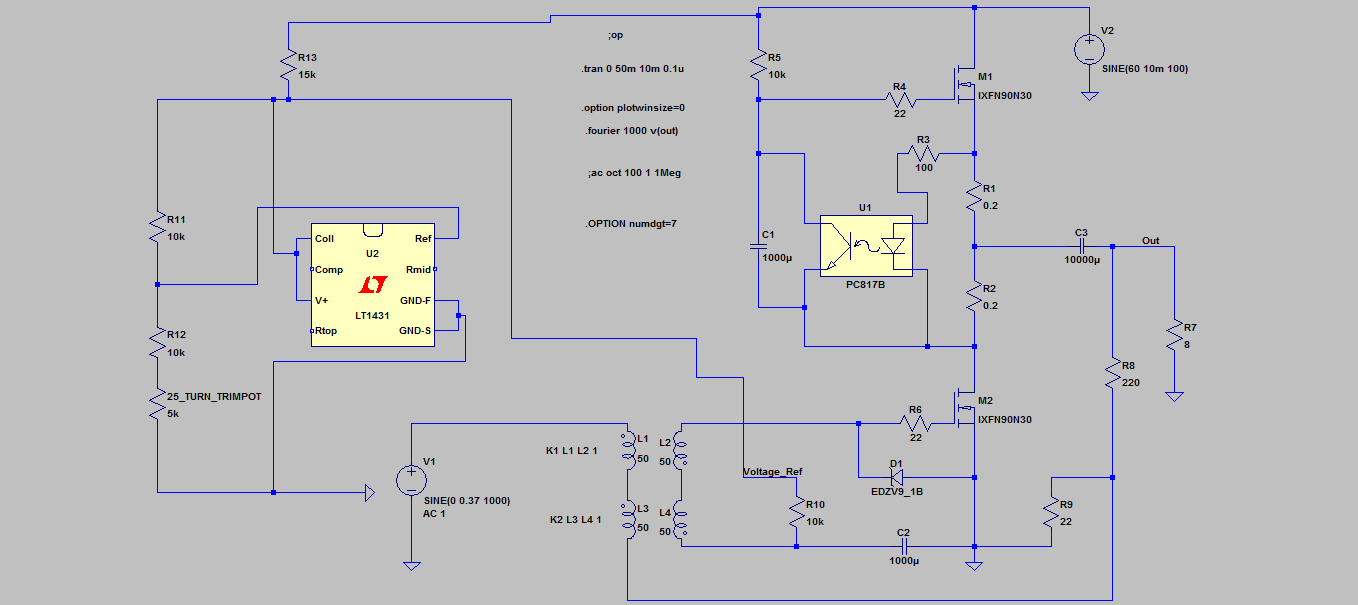
Looks nice - what are your R wattage asuumptions for R3 to 6, 9 and 10? Thanks.
Looks nice - what are your R wattage asuumptions for R3 to 6, 9 and 10? Thanks.
CMF55
That would be nice.
😉
L = 2.2H, I measured this, incredible high …..
each winding = 29R
Cprimary to secondary = 14nF
Thanks.L = 2.2H, I measured this, incredible high …..
each winding = 29R
Cprimary to secondary = 14nF
L needs to be high to ensure the published flat frequency response
Is there a difference between the pc817b and the 4n37 that is in the
original circuite ?
Use 4n37 or equivalent.
Whatever is easiest to obtain is fine.
Paralleling devices is fine but then you need to match them so in the end it won't really be cheaper.
You may as well purchase Nelson's recommended parts.
Paralleling devices is fine but then you need to match them so in the end it won't really be cheaper.
You may as well purchase Nelson's recommended parts.
Ixys only outside of Brazil, and would be very expensive due to taxes 🙁
- Status
- Not open for further replies.
- Home
- Amplifiers
- Pass Labs
- BAF 2015 Coverage