These are the caps on the output stage of the YJ Blue board.
I've got some inductors which i am keen to try, but it seems that i might have to remove and refit the caps to get the inductors on the board.
I've got some inductors which i am keen to try, but it seems that i might have to remove and refit the caps to get the inductors on the board.
You're more likely to have damage from heat on the PCB or the leads getting melted into a strange form. So what I mean is still try to be efficient, even if the film caps can take some heat.
SMD film caps can be reused. The problem is not breaking them during removal. Tweezer irons or dual iron wielding is the way to go. You have to be quick, but it works. I watched a guy dual wield irons and move some resistors around the same board. I think he had some practice under his belt however.
SMD film caps can be reused. The problem is not breaking them during removal. Tweezer irons or dual iron wielding is the way to go. You have to be quick, but it works. I watched a guy dual wield irons and move some resistors around the same board. I think he had some practice under his belt however.
I've got some inductors which i am keen to try, but it seems that i might have to remove and refit the caps to get the inductors on the board
Almost impossible NOT to melt the caps when changing the inductors, particularly the 2 inner ones, on the YJ BB, so cap removal is the best bet
However, be gentle because the round solder tabs around the holes on the underside of the YJ BB [& on the bulk of cheap Chinese PCBs] pull off very easily. Before removal, I usually add solder to the pins I want to remove, then use a sucker to remove as much solder as possible ... then very gently pull the top of the cap, with the soldering iron on the cap leg on the underside. After you do it a few times, you'll master it 🙂
From the data sheet, page 15:
"The tolerance of the input resistor value is ±20%..."
Would you use a 20% tolerance resistor in a HPF?
Not generally, but in this case: yes, absolutely.

I don't think 0.6 dB difference under the cutoff frequency annoys anybody. This is not a Brüll-Kjaer acoustic measurement system.
Hello, thanks for your advice. I've changed my schematic. It will probably still have some beginnersmistakes. So I'd like to hear your feedback. I'm familiar with the theory but implementing it practically is still somewhat hard for me, I easily forget some stuff that I need to keep in mind as I don't have experience in designing circuits.
Anyway, i've included a pdf file of my schematic. I chose for an active crossover and using both the channels as some of you recommended. I've used a 4th order Linkwitz-Riley crossover at 3.5Khz. I've ditched the 4th order butterworth highpass filter and used the input cap as an extra highpass filter.
Some questions I have:
Q1: in the treble/bass circuit (I found the schematic on a dutch electronics forum, and I understand the working), they biased the non-inverting input with 2 10K resistors (R1 and R2). Should I raise the value to 100K for limiting the supply current through the divider?
Q2: I've biased the signal again before the split into the LPF and HPF. Is this ok, or should I do it after the split? I did it like this as the voltage will stay the same as it's parallelled so I guess it doesn't matter but I'm not sure. Also, should I add a buffer behind it? Is 1uF ok for bypass capacitor or should it be higher?
Q3: I've set the gain at 26dB. This gives an input impedance of 30kOhm. So when using a 1nF capacitor I get a flat response down to 53Hz or with a 0.82nF capacitor its down to 65Hz. Power wise, how will this affect the current draw from the battery? Will it save me some current or is it negligible and I should get with the 1nF capacitor to extend my bass?
For the tweeter, it's already highpassed. What value should I use here?
Q4: I've got rid of the jumpers for the modulation frequency selection as it will take some place on the pcb. I've googled the AM stations in Belgium but they don't send on those frequencys anymore. Is 400kHz ok? It's the easiest way to connect those inputs without needing to get Vcc at one of the inputs.
Other remarks on my design is appreciated.
Thanks for your time 🙂
Attachments
-You could connect the modsel pin to the sdz/fault for easier layout.
-The 2200uF cap doesn't add much when you already have two 470uF caps.
-You could add another opamp to cut the low end. With a higher order it will help much more to save battery and reduce excursion than just the input caps (especially handy with ported enclosures).
-You could go with a quad op amp instead of a couple of the single ones to save on board space, complexity and cost.
Hello, thanks for your advice. I've changed my schematic. It will probably still have some beginnersmistakes. So I'd like to hear your feedback. I'm familiar with the theory but implementing it practically is still somewhat hard for me, I easily forget some stuff that I need to keep in mind as I don't have experience in designing circuits.
Anyway, i've included a pdf file of my schematic. I chose for an active crossover and using both the channels as some of you recommended. I've used a 4th order Linkwitz-Riley crossover at 3.5Khz. I've ditched the 4th order butterworth highpass filter and used the input cap as an extra highpass filter.
Some questions I have:
Q1: in the treble/bass circuit (I found the schematic on a dutch electronics forum, and I understand the working), they biased the non-inverting input with 2 10K resistors (R1 and R2). Should I raise the value to 100K for limiting the supply current through the divider?
The resistance alone is not very important, but time constant is. Too much makes settling too slow, too small doesn't give smooth enough bias voltage.
Bias filter can be 2 nd order, enabling being faster and more effective.
C1 can be electrolytic.
Q2: I've biased the signal again before the split into the LPF and HPF. Is this ok, or should I do it after the split? I did it like this as the voltage will stay the same as it's parallelled so I guess it doesn't matter but I'm not sure. Also, should I add a buffer behind it? Is 1uF ok for bypass capacitor or should it be higher?
You need only 1 bias voltage, but it must be good (smooth and low impedance). 2 different bias voltage is a source of problems. In this particular case it's totally wrong, won't even work. Think bias voltage as a new GND (=reference potential) for all of the analog circuits! Everything you've connected to GND up to now, should be connected to bias voltage, except for OPA power supply! (If you can't make this properly, consider making a negative power supply rail. It's not very difficult, you only need an NE555 and some capacitors+diodes. This is a better solution in terms of signal integrity.)
Buffer: you don't need here, but suggested in front of trebble/bass circuit, otherwise input capacitor will form a variable HPF with the variable input impedance of this stage. Basically you need coupler capacitors only where changing bias voltage. 1: on input, 2: between analog front-end and ClassD amp. 1st can be a part of a 2nd order active HPF, serving also as a buffer stage for treble/bass. ClassD input cap can be tuned slightly under the desired "subsonic" cutoff freq.
R7 is unneccessary.
I suggest you to choose higher impedances in filters. 10...100k
Q3: I've set the gain at 26dB. This gives an input impedance of 30kOhm. So when using a 1nF capacitor I get a flat response down to 53Hz or with a 0.82nF capacitor its down to 65Hz.
You mean 1 uF and 5.3 Hz? Recalculate please!
Power wise, how will this affect the current draw from the battery? Will it save me some current or is it negligible and I should get with the 1nF capacitor to extend my bass?
See above my recommendation. 1st order is definitely more than nothing, but if you really need saving power, you have to try more values, and 2-3rd order can be better. It depends on the woofer design, acoustic environment, music, and personal taste. The later the more important... 🙂
Basically power consumption will be surprisingly low for you - I guess. With 7 Ah you can expect about a day of playtime at full volume (with light clipping).
For the tweeter, it's already highpassed. What value should I use here?
Almost any value is OK, but I would use it also as a part of the crossover.
Q4: I've got rid of the jumpers for the modulation frequency selection as it will take some place on the pcb. I've googled the AM stations in Belgium but they don't send on those frequencys anymore. Is 400kHz ok? It's the easiest way to connect those inputs without needing to get Vcc at one of the inputs.
I have no info about this.
Other remarks on my design is appreciated.
I think 4th order filter is a little too much, I will make mine 3rd order including natural falloff of bass speaker.
Big buffer capacitor is always a good thing in amps.
Be careful, protect the circuit against reverse polarity, and secure battery (and wiring) with fuse! 1 amp is enough and effective.
Volume pot is better in front of trebble/bass circuit, because this way you can avoid overdriving it in case of high input voltage and emphasized bass.
Trebble channel can be attenuated according to sensitivity differences, before and/or after its HPF.
Shallen-key filter can be modified to give gain. It can be beneficial in the lower channel.
Thanks for your time 🙂
You're welcome!
-You could connect the modsel pin to the sdz/fault for easier layout.
-The 2200uF cap doesn't add much when you already have two 470uF caps.
-You could add another opamp to cut the low end. With a higher order it will help much more to save battery and reduce excursion than just the input caps (especially handy with ported enclosures).
-You could go with a quad op amp instead of a couple of the single ones to save on board space, complexity and cost.
Thanks.
-good tip, don't know how i missed that
-ok
-i have a fifth order lowpass at the moment, i guessed it was already high enough. see the picture i've added of my enclosure design. It's 20l tuned at 85Hz, - i didn't add the lpf to it
-the lpf and hpf are using dual opamps. i avoided the quad opamps as i didn't want to overcomplex my pcb layout. now i can easily put each filter at a side
The resistance alone is not very important, but time constant is. Too much makes settling too slow, too small doesn't give smooth enough bias voltage.
Bias filter can be 2 nd order, enabling being faster and more effective.
C1 can be electrolytic.
You need only 1 bias voltage, but it must be good (smooth and low impedance). 2 different bias voltage is a source of problems. In this particular case it's totally wrong, won't even work. Think bias voltage as a new GND (=reference potential) for all of the analog circuits! Everything you've connected to GND up to now, should be connected to bias voltage, except for OPA power supply! (If you can't make this properly, consider making a negative power supply rail. It's not very difficult, you only need an NE555 and some capacitors+diodes. This is a better solution in terms of signal integrity.)
Buffer: you don't need here, but suggested in front of trebble/bass circuit, otherwise input capacitor will form a variable HPF with the variable input impedance of this stage. Basically you need coupler capacitors only where changing bias voltage. 1: on input, 2: between analog front-end and ClassD amp. 1st can be a part of a 2nd order active HPF, serving also as a buffer stage for treble/bass. ClassD input cap can be tuned slightly under the desired "subsonic" cutoff freq.
R7 is unneccessary.
Thanks for the explenation. I don't understand it quite yet. I don't have my electronics textbook next to me atm, I will look at it tomorrow. I hope I'll also see my teacher to ask for a quick lesson on bias voltage.
I added that second bias as I thought it was needed after C8, but I guess C8 doesn't need to be there.
So when working with bias voltages I need 2 seperate grounds on my pcb?
Ok, I'll recalculate. I've designed the filters with filter pro from TI and I guessed they where ok.I suggest you to choose higher impedances in filters. 10...100k
Sorry, I should be more clear and indeed 1uF. The datasheet says that in order to get a flat response from x Hz, you need to choose the input cap so that it will act as a hpf at x/10 Hz.You mean 1 uF and 5.3 Hz? Recalculate please!
So 1uF input cap gives indeed 5,3Hz hpf but in the end it will give a flat response from 53Hz.
It will be for outdoors mostly. Music taste is broad, but mostly hiphop and dub. So now that I think of it, is should lower my highpass to 53Hz or 65Hz. The woofer is rated from 55Hz to 5.5kHz.See above my recommendation. 1st order is definitely more than nothing, but if you really need saving power, you have to try more values, and 2-3rd order can be better. It depends on the woofer design, acoustic environment, music, and personal taste. The later the more important... 🙂
Basically power consumption will be surprisingly low for you - I guess. With 7 Ah you can expect about a day of playtime at full volume (with light clipping).
OkAlmost any value is OK, but I would use it also as a part of the crossover.
-I've chosen for a 4th order so I can use the same cut off freq for both filters. Adding them together will give me a flat response.I think 4th order filter is a little too much, I will make mine 3rd order including natural falloff of bass speaker.
Big buffer capacitor is always a good thing in amps.
Be careful, protect the circuit against reverse polarity, and secure battery (and wiring) with fuse! 1 amp is enough and effective.
Volume pot is better in front of trebble/bass circuit, because this way you can avoid overdriving it in case of high input voltage and emphasized bass.
-Big buffer capacitors, which capacitors you meant by this?
-Yes I know, I first wanted to complete this schematics. I will ask my teacher how to handle this best.
-Ok.
I didn't change the gain of the lpf as i didn't want to overdrive the output.Trebble channel can be attenuated according to sensitivity differences, before and/or after its HPF.
Shallen-key filter can be modified to give gain. It can be beneficial in the lower channel.
The tweeter has indeed a higher sensitivity than the woofer. Can't i change the gain in the filter aswel?
I can maybe add a series and parallel resistor in the feedback loop of both filters so that i can change the gain of both the channels if needed afterwards.
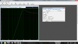
@irribeo i've used a higher capacitor and lower inductor than that. The cutoff frequency is 27kHz and it has an impedance of 1.7Ohm
Attachments
Last edited:
Swedgin;450318 -i have a fifth order lowpass at the moment said:"to cut the low end" means HPF.
So when working with bias voltages I need 2 seperate grounds on my pcb?
No. I didn't mention PCB. I think you should think about DC operating point and signal voltages. You have to understand how your circuit works first.
Sorry, I should be more clear and indeed 1uF. The datasheet says that in order to get a flat response from x Hz, you need to choose the input cap so that it will act as a hpf at x/10 Hz.
Yes, if you need perfectly flat response. But you want to filter, dont you?
It will be for outdoors mostly. Music taste is broad, but mostly hiphop and dub...
Experiment! Nobody can tell it.
-Big buffer capacitors, which capacitors you meant by this?
The biggest.
I didn't change the gain of the lpf as i didn't want to overdrive the output.
There is a volume pot...
The tweeter has indeed a higher sensitivity than the woofer. Can't i change the gain in the filter aswel?
Not really.
I can maybe add a series and parallel resistor in the feedback loop of both filters so that i can change the gain of both the channels if needed afterwards.
Problematic this way. Affects filter Q.
Hello everybody 🙂
I’ve just received the dual chip board:
TPA3116 D2 Dual Channel 2*100W Digital Audio Amplifier Module for Arduino | eBay
I’ve tried it for few hours and seems good, considering the price.. I would use this board without pot (with a tube preamp) but the bump is worse than the YJ blue, have you any suggestion to fix this problem or the easiest way is to use the switch pot also in tpa board?
Many thanks and sorry for my english 🙂
I haven't built mine in to anything but have noticed no turn-on thump when using the on/off/volume pot. Maybe there's a way of adding a delay circuit?
No problems with the English either. It's better than most people use on "the social media" 🙂
No problems with the English either. It's better than most people use on "the social media" 🙂
Last edited:
I haven't built mine in to anything but have noticed no turn-on thump when using the on/off/volume pot. Maybe there's a way of adding a delay circuit?
No problems with the English either. It's better than most people use on "the social media" 🙂
Thanks Jerms, by a mothertongue is much appreciated 🙂
About thump i agree with you: if i use on/off alimentation in first, and then the on/off of TPA there's no thump, compared to YJ blue it's perfect.
Instead, if i turn on the pot at max in first (is it like take off the pot and short the channels, right?) and then i turn on the alimentation the thump is very hard.
I don't know if it's possible to add a similar "Giancarlo circuit" also on this board, i haven't enough knowledge to verificate this option..

Populated my PCB today, but can't get it working. It's in 1SPW/PBTL config with a FB output filter. There is no short on either the input or the output, it consumes 2.4mA but gives no output. I'll troubleshoot it further tomorrow when I have time, any suggestions?
An externally hosted image should be here but it was not working when we last tested it.
An externally hosted image should be here but it was not working when we last tested it.
- Home
- Amplifiers
- Class D
- TPA3116D2 Amp