Are there any build threads using linear power supplies? What sort of VA rated toroidal transformer would be required?
Hello
For a project at school I need to make a class D amp. I've chosen the tpa3130 to use as base. (I found later that the 3116 has more output, but the chip was already ordered).
Anyway, this is my first attempt at building such an amp and I'm going to use it for a portable 2way system with a Fane Sovereign 8-225 8Ohm woofer and an eminence apt80 8Ohm tweeter with a crossover frequency of 3.5kHz. This all is going to get powered by a 12V 7Ah (or 10Ah, not sure yet) battery.
Is 10 W output power enough?
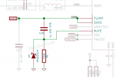
I've made my eagle schematic and I'd love if someone here can give his opinion on it.
Zippyshare.com - schema, snubbermod.sch
Some people don't use eagle...
Some more explanation:
-first there is a 4th order active Butterworth highpass filter @70kHz to cut the lower frequencies. this is to limit the lower frequencies and save some battery
I hope Hz, not kHz.
- i've used the bootstrap snubber mod, i'm just not sure if i can connect positive and negative pin of each output before or after the LC filter. atm I need 2 inducturs instead of 4.
Not clear what do you mean without seeing schematic.
- the LC filter is tuned at 28kHz with an impendance of 1.7Ohm
- I'm using this chip in mono, and pbtl mode
Why paralel at 8 ohm load? It's 4 times oversizing. You'd better use 2 channels with an active crossover for driving speakers separately. Much better quality and higher power. Also 4 ohm bass+midrange speaker would be better (I quess you want as much power as you can).
-for input dc de-coupling caps:
2x
capacitor 10µF, >10V, smd, >x5r
Generally X5R is not good enough for audio coupling. But with this brutal oversizing dielectric quality is the smaller problem.
-bootstrap caps:
4x
0.22 µF, ± 10%, X7R, 250 V, 1210
16 V is perfectly enough, but it's better be small in size.
-for snubber:
2x
SMD Multilayer Ceramic Capacitor, CGA Series, 3.3 µF, ± 10%, X7R, 50 V, 1210
Why so high? It might burns R15...R18 at high audio freq.
Thanks for your time 🙂
Hi JonesySA,
I'm using a (AU market) GME PSA1210 13.8v 11Amp supply modified with low ESR caps with very satisfactory results. Spec'd at 5 amps continuous current @ 13.8v. Given its continuous current rating, i wouldnt want to dip much below this.
I'm using a (AU market) GME PSA1210 13.8v 11Amp supply modified with low ESR caps with very satisfactory results. Spec'd at 5 amps continuous current @ 13.8v. Given its continuous current rating, i wouldnt want to dip much below this.
Are there any build threads using linear power supplies? What sort of VA rated toroidal transformer would be required?
Thanks for your reply.
For now yes. It's a first project and I don't want to put too much money in it. The 3130 is rated at 2x 15W @15V, 8 Ohm, so in PTBL mode this would be a bit higher than 10W with 12V?
I'm sorry didn't think of that. I've attached a pdf file of my schematic.
Yes, mistake by me.
See pdf and/or link to post
There aren't any 4 Ohm 8" woofers on thomann in my pricerange <70 euro.
If I understand it correctly, if I bridge the outputs, I get twice the power. At the moment I'm using a passive 2nd order Butterworth highpass and lowpass in parallel for driving the drivers. If I use the 2 outputs, wouldn't my tweeter (105db/W/m) go alot loader than my woofer (95db/W/m)?
I'm sorry, I wasn't clear, I meant the output LC filter for filtering the switching frequencies.
Ok, good to know I should pick X7R.
Hm wow, another mistake of me. I meant for the LC output filter. For the snubber, I'm using 330pF/50V smd.
Changed the mistakes in my original post --> apperently i can't edit my original post.
Is 10 W output power enough?
For now yes. It's a first project and I don't want to put too much money in it. The 3130 is rated at 2x 15W @15V, 8 Ohm, so in PTBL mode this would be a bit higher than 10W with 12V?
Some people don't use eagle...
I'm sorry didn't think of that. I've attached a pdf file of my schematic.
I hope Hz, not kHz.
Yes, mistake by me.
Not clear what do you mean without seeing schematic.
See pdf and/or link to post
Why paralel at 8 ohm load? It's 4 times oversizing. You'd better use 2 channels with an active crossover for driving speakers separately. Much better quality and higher power. Also 4 ohm bass+midrange speaker would be better (I quess you want as much power as you can).
There aren't any 4 Ohm 8" woofers on thomann in my pricerange <70 euro.
If I understand it correctly, if I bridge the outputs, I get twice the power. At the moment I'm using a passive 2nd order Butterworth highpass and lowpass in parallel for driving the drivers. If I use the 2 outputs, wouldn't my tweeter (105db/W/m) go alot loader than my woofer (95db/W/m)?
I'm sorry, I wasn't clear, I meant the output LC filter for filtering the switching frequencies.
I've followed this post and the one after thatGenerally X5R is not good enough for audio coupling. But with this brutal oversizing dielectric quality is the smaller problem.
Ok, good to know I should pick X7R.
I've followed this post16 V is perfectly enough, but it's better be small in size.
[/QUOTE]Why so high? It might burns R15...R18 at high audio freq.
Hm wow, another mistake of me. I meant for the LC output filter. For the snubber, I'm using 330pF/50V smd.
Changed the mistakes in my original post --> apperently i can't edit my original post.
Attachments
Last edited:
Youre welcome.Thanks for your reply.
For now yes. It's a first project and I don't want to put too much money in it. The 3130 is rated at 2x 15W @15V, 8 Ohm, so in PTBL mode this would be a bit higher than 10W with 12V?
Basically amplifiers are voltage sources. I=V/R, P=I*V. Paralelling increase allowable current, but achieving higher power you need lower impedance.
No, power is given already in bridge.If I understand it correctly, if I bridge the outputs, I get twice the power.
At the moment I'm using a passive 2nd order Butterworth highpass and lowpass in parallel for driving the drivers. If I use the 2 outputs, wouldn't my tweeter (105db/W/m) go alot loader than my woofer (95db/W/m)?
It's not a problem. It is louder already anyway, but if you go to active x-over, then you can adjust gain easily and without power loss. Much better this way, smaller and cheaper also.
Foil capacitor is the right choice, but much lower valueI've followed this post and the one after that
Ok, good to know I should pick X7R.
I've followed this post
Hm wow, another mistake of me. I meant for the LC output filter. For the snubber, I'm using 330pF/50V smd.
Changed the mistakes in my original post --> apperently i can't edit my original post.
Swedgin!
Generally bigger input cap can be good in order to get good bass response. But since you deliberately cut bass under 70 Hz, it's qiute pointless.
Think about power supply of OPAs! Negative power supply voltage must be significantly lower than the inputs and outputs of the IC! If you change references here from GND to a higher level (filtered very well), then you can omitt C7 and C8. Not only IC4A needs this offset, but all of them! (Or none of them, but then you need symmetrical supply.)
Basically amplifiers are voltage sources. I=V/R, P=I*V. Paralelling increase allowable current, but achieving higher power you need lower impedance.
Hm, I'm not quite sure I understand. If the allowable current increases, why doesn't the power increases aswel?
V = RI and V is fixed, so if current increases, R has to decrease, right? But what happens if R stays fixed and the current increases?
Foil capacitor is the right choice, but much lower value
I thought I read somewhere that the highpass of this capacitor changes the characteristics of the higher frequencies aswel. So if I use a 1uF instead of 10uF capacitor, it still can sound different even with the 70Hz highpass. I can't seem to find the post though.
Current can't increase with fixed V & R, otherwise ohms law wouldn't work anymore. 🙂
Power doubles if you half the load resistance. As you can't go 2ohms while in 2 channel stereo, you can do in PBTL. Only then power doubles.
But its the same to have 2x 4ohm speakers, each on one channel BTL, or both wired in parallel connected to PBTL. A benefit from PBTL, even with one 4 ohm speaker is, you'll spread the current on both bridges and cancel out some "noise", same like if you parallel transistors to equalize noise-floor.
Current can't increase with fixed V & R, otherwise ohms law wouldn't work anymore. 🙂
Wow, I feel stupid, I don't know where I was then, that's the real basic 😱
Power doubles if you half the load resistance. As you can't go 2ohms while in 2 channel stereo, you can do in PBTL. Only then power doubles.
But its the same to have 2x 4ohm speakers, each on one channel BTL, or both wired in parallel connected to PBTL. A benefit from PBTL, even with one 4 ohm speaker is, you'll spread the current on both bridges and cancel out some "noise", same like if you parallel transistors to equalize noise-floor.
Thanks for you explantion.
@Pafi, good tip on the supply voltage of the opamps. The three opamps are on the same chip, so it's only needed once
Wushuliu was quoted on filmcap values that looked big to Pafu, his cuttof frequencies aren't very low however, Wushuliu can also be quoted preferring and using the 36dB gainsetting for his ampboards, when 70hz unattenuated is your goal you already need 2.2uF (2.5) filmcaps in that setup. Select lower gainsettings and lower value capacitors can be used to produce same output.
Hey guys, awhile back a handful of you built my PSU design to use with this TPA3116. And several wanted to know when a PCB would come out. ChrisMmm comments on PSU.
Well I've used the PSU in a few things now, and would like to have a bunch printed so I've started an IndieGoGo for whomever is interested.
Well I've used the PSU in a few things now, and would like to have a bunch printed so I've started an IndieGoGo for whomever is interested.
Swedgin,
As soon as you decide value of gain, you can consider input cap as part of the intended HPF, and choose an exact value, not a brutally oversized one. This way you can decrease turn-on pop duration, make it cheaper and smaller, and win an order of HPF for free. I think 3rd order must be enough, so with the same part count you can also make the active X.
As soon as you decide value of gain, you can consider input cap as part of the intended HPF, and choose an exact value, not a brutally oversized one. This way you can decrease turn-on pop duration, make it cheaper and smaller, and win an order of HPF for free. I think 3rd order must be enough, so with the same part count you can also make the active X.
Inductor tolerance
Hello,
I have purchased a few 10uH (+/- 20%) inductors to install on a YJ board and one of them has measured at 9uH (as opposed to 10uH).
Would this be usable on the board - or do i need to get another inductor ?
Hello,
I have purchased a few 10uH (+/- 20%) inductors to install on a YJ board and one of them has measured at 9uH (as opposed to 10uH).
Would this be usable on the board - or do i need to get another inductor ?
Swedgin,
As soon as you decide value of gain, you can consider input cap as part of the intended HPF, and choose an exact value, not a brutally oversized one. This way you can decrease turn-on pop duration, make it cheaper and smaller, and win an order of HPF for free. I think 3rd order must be enough, so with the same part count you can also make the active X.
From the data sheet, page 15:
"The tolerance of the input resistor value is ±20%..."
Would you use a 20% tolerance resistor in a HPF?
For turn on pop there is giancarlo's addition, what remains is turn off pop
To fix both problems, go for this circuit:
Source
It also has the advantage of having a PVCC independent time-constant.
@DUG,
getting power-inductor better than +/-10% is a bit difficult. Buying a bunch and measuring to match them can be a solution. (But L=f(I) must also be considered)
Btw.
anyone noticed to new automotive versions of TPA3116D2/TPA3118D2, named TPA3116D2-Q1/TPA3118D2-Q1? (-40-125°C)
http://www.ti.com/product/tpa3116d2-q1/description
Attachments
Last edited:
Yes Q1 is funny, one needs 1nF coupling caps for signalinput, also for bass amp. Booster designs do use 50V bootstraps, so not all is funny 🙂
Can film capacitors be desoldered (without damage) and reused (resoldered) ?
Yes
- Home
- Amplifiers
- Class D
- TPA3116D2 Amp