Reference and photo of frame grid with 37kHz microphonic resonance.
http://www.thevalvepage.com/valvetek/microph/ValveMicrophony_pt1.pdf
http://www.thevalvepage.com/valvetek/microph/ValveMicrophony_pt1.pdf
Nice ref, thanks. I was wondering what your avatar was!Reference and photo of frame grid with 37kHz microphonic resonance.
http://www.thevalvepage.com/valvetek/microph/ValveMicrophony_pt1.pdf
"I'd suggest the grid wire sections are the only structure that could generate the 12-17kHz observed microphonics by Scott."
That may bode poorly for using the larger frame grid tubes then, an even lower resonance range likely.
Maybe dunk the operating tube in a pool of some gooey silicone oil. Or an Aerogel suspension.
A small note on using graphene for grids. The pure graphene is near superconducting and may prevent, by eddy current generation, any electrons from passing through perpendicularly (opposing magnetic field generated). There are now several other more semiconducting mono-layer films like MoS2 or nitrides or graphane derivatives that might meet the requirements. Some are easier to make as well.
Last edited:
How is mechanical damping outside supposed to affect a resonance inside?Smoking-amp said:Maybe dunk the operating tube in a pool of some gooey silicone oil. Or an Aerogel suspension.
The pure graphene is near superconducting...
What does that mean? Superconducting transitions are sharp.
"How is mechanical damping outside supposed to affect a resonance inside?"
One would want to prevent acoustic energy from reaching the tube in the 1st place. But the transfer from envelope to internal resonator is a two way street, so internal acoustic energy can still be absorbed externally (albeit slowly). If only a tiny amount makes it in, then that could be enough to soak it up again.
-------------------------------
"What does that mean? Superconducting transitions are sharp."
Its not actually "superconductive", but exhibits enormous electron mobility if defect free. It CAN be made superconductive though.
From Wikipedia:
""" Graphene displays remarkable electron mobility at room temperature, with reported values in excess of 15000 cm2⋅V−1⋅s−1. Hole and electron mobilities were expected to be nearly identical. The mobility is nearly independent of temperature between 10 K and 100 K, which implies that the dominant scattering mechanism is defect scattering. Scattering by graphene's acoustic phonons intrinsically limits room temperature mobility to 200000 cm2⋅V−1⋅s−1 at a carrier density of 1012 cm−2, 10×106 times greater than copper.
The corresponding resistivity of graphene sheets would be 10−6 Ω⋅cm. This is less than the resistivity of silver, the lowest otherwise known at room temperature.
As a consequence, at low energies, even neglecting the true spin, the electrons can be described by an equation that is formally equivalent to the massless Dirac equation. Hence, the electrons and holes are called Dirac fermions. .........................
Here vF ~ 106 m/s (.003 c) is the Fermi velocity in graphene, which replaces the velocity of light in the Dirac theory;
In 2015 lithium-coated graphene exhibited superconductivity, a first for graphene. """
---------------------
The C bonds perpendicular to the graphene sheet allow it to be chemically customized. From insulator (graphane) all the way to superconductor.
I'm not sure if the native electron mobility would be enough to eddy current repel perpendicular electrons, especially with 3% C fermions restricting the diameter of interaction. It might set an energy threshold for impinging electrons though. Probably related to the wavelength of the electron versus interaction diameter. I'm sure there is some literature on this for accelerator applications somewhere, would be well characterized by now.
Can always just use cheap, defect riddled, graphene for the grid. Not too hard to make.
Last edited:
and there's field emission cathodes, and optoelectronic ones. The latter require a lot of photons for useful currents 🙂
That Nutube device is probably using the field emission cathode approach. Carbon nanotube paint commercially successful for flat panels. It has limitations from maximum current vaporizing the nanotube ends though. And probably has limitations on how close a grid can be located to the surface. They could be noisy too from the concentrated field emitters. Should include a Nutube on the list for noise testing.
The TiO2 thin film emitters were just short of room temperature 15 years ago, with emission density competitive with SS. About 10 years ago they made it to room temperature using multiple thin film layers. (its tunneling assisted thermionic emission, no sharp points, perfectly flat) Haven't followed them for the last ten years, but you can probably make a TO-247 sized power tube by now using CVD and etching technology. (the best cathode stuff may be classified or at least proprietary by now though, microwave satellite tubes) With a thin flat assembly, probably can run at low voltages and high currents too. (no more OT $) I suspect the uniform flat cathode would be low noise (Flicker Noise at least).
Another flat grid approach would be to use laser perforated sheet metal, like used for shadow grids/masks in color TV tubes, once upon a time.
Last edited:
again, great post.That Nutube device is probably using the field emission cathode approach. Carbon nanotube paint commercially successful for flat panels. It has limitations from maximum current vaporizing the nanotube ends though. And probably has limitations on how close a grid can be located to the surface. They could be noisy too from the concentrated field emitters. Should include a Nutube on the list for noise testing.
The TiO2 thin film emitters were just short of room temperature 15 years ago, with emission density competitive with SS. About 10 years ago they made it to room temperature using multiple thin film layers. (its tunneling assisted thermionic emission, no sharp points, perfectly flat) Haven't followed them for the last ten years, but you can probably make a TO-247 sized power tube by now using CVD and etching technology. (the best cathode stuff may be classified or at least proprietary by now though, microwave satellite tubes) With a thin flat assembly, probably can run at low voltages and high currents too. (no more OT $) I suspect the uniform flat cathode would be low noise (Flicker Noise at least).
Another flat grid approach would be to use laser perforated sheet metal, like used for shadow grids/masks in color TV tubes, once upon a time.
Woops, small error earlier on the graphene mobility. 0.003 C (from Wiki) would be 0.3% of C velocity, not 3% as I said.
That would put the wavelength lambda of the lattice electrons at 8.08 Angstrom. And the circumference of the benzene ring is around 8.5 Angstroms (probably related, so that's the interaction region). And that's about 4.6 electron volts. So my CRUDE guess would be that any threshold for a penetrating electron would be in the vicinity of 4.6 eV (electron Volts). (ie, electron lambda fits thru the benzene ring) So that would be a minimum positive bias for grid1 to get conduction through the grid. (Gee, 4.6 V sounds like a Mosfet gate offset, a Vacuum Enhancement Mosfet.) So plain graphene is probably working OK for a grid.
Lambda = h/mv
Last edited:
The Nutube is just a minor variant on the usual VFD display, which has a hot cathode (barely hot enough to be visibly glowing) using several parallel filaments, a control grid, and phosphor-coated anode segments. Sounds like a triode to me, just ditch the phosphor. It would be interesting to grab a surplus display and try some curve tracing with the plate segments tied in parallel. I suspect that the plate segments are switched in the usual VFD display, with the grid remaining at constant potential.
I was more or less right - check out this simple tutorial from Noritake...
https://www.noritake-elec.com/display/vfd_operation.html
https://www.noritake-elec.com/display/vfd_operation.html
Fascinating. So the 400 dollar price tag probably represents how little Noritake really wanted to make something different!
Sure wish they (Korg) would publish characteristic curves rather than a bunch of blather about rich bla bla sound.
Sure wish they (Korg) would publish characteristic curves rather than a bunch of blather about rich bla bla sound.
I betcha you could take a classic VFD and get some sounds/curves out of it, though the gain might be a bit low, as the hexagonal grid mesh traditionally used might be a bit coarse by tube standards. Still it's planar, and there's a lot of grid area, though not so much on the plate side of things. Noritake was possibly looking for some extra guaranteed income, as liquid crystals and OLEDs are no doubt eating into their traditional business.
Having said that, they're cheap, long lifetime, tolerate a wide temperature range, and don't wash out under sunlight.
The display on that NAD CD player that Corey Greenberg got so crazy about had a display that was the first thing to fail (but not the last). But it was probably the driver/power supply.
On all the consumer gear I've had over the years, no VFD has faiied, ever, no matter how cheap the product.
Hi Everyone,
I updated the list of measurements on the downloads page of my website to include measurements on the Russian RU-6H16 (6N16). This is a sub-miniature medium-mu dual triode, suggested and sent to me by Koifarm. Thanks Ronny, and sorry it took so long. The RU-6H16 is respectable performer, especially for a sub-miniature type, but not especially low noise compared to other tubes on the list.
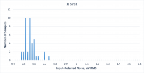
I also included many more measurements of the JJ 5751, which continues to show good noise performance. There were 3 high noise tubes (which I discarded) out of the 12 new ones I measured, which is unfortunately beginning to seem like a typical ratio. I updated the histogram for the 5751, below. The histogram does not include the 3 high noise tubes.
Scott
Downloads – Tavish Design
I updated the list of measurements on the downloads page of my website to include measurements on the Russian RU-6H16 (6N16). This is a sub-miniature medium-mu dual triode, suggested and sent to me by Koifarm. Thanks Ronny, and sorry it took so long. The RU-6H16 is respectable performer, especially for a sub-miniature type, but not especially low noise compared to other tubes on the list.
I also included many more measurements of the JJ 5751, which continues to show good noise performance. There were 3 high noise tubes (which I discarded) out of the 12 new ones I measured, which is unfortunately beginning to seem like a typical ratio. I updated the histogram for the 5751, below. The histogram does not include the 3 high noise tubes.
Scott
Downloads – Tavish Design
Attachments
- Home
- Amplifiers
- Tubes / Valves
- List of Tube Noise Measurements - please nominate lowest noise tubes