Member
Joined 2009
Paid Member
Where you get this pcb and schematic?My KILLER AMP.Borys Thanks.Tomorrow sound test.
Here,and Borys sent me Eagle files
http://www.diyaudio.com/forums/solid-state/238593-ska-gb150d-now-public-domain-55.html#post3790176
http://www.diyaudio.com/forums/solid-state/238593-ska-gb150d-now-public-domain-55.html#post3790176
platon
Thanks.
Make sure zobel network is connected on the board! It is part of the compensation and must be connected in this case.
Lookinkg forward for listening tests.
Regards Peter
Thanks.
Make sure zobel network is connected on the board! It is part of the compensation and must be connected in this case.
Lookinkg forward for listening tests.
Regards Peter
Does this mean that the revised version may be a candidate for the same source resistor bypass diodes as the F5 Turbo V2? Oh whoops.. this was meant as a reply to Andrew T's comment on the inclusion of source resistors in the GB150D. I am a bit newb to this forum malarkey. 8)
Last edited:
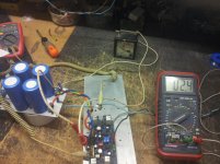
DC offset 3mV.Sound super..many details,bass.
do you have zener mode? 🙂
Hi,
Here are the BOM and the schematics for Jim's Audio PCB.
Those who are building this amp with Jim's boards should follow this BOM because there are diferences to Greg's boards.
Please use 2SC2240BL/2SA970BL and don't forget the signal ground wire from input to main star ground. Jim forgot to place a hole on the board for this connection.
Paulo.
Attachments
Last edited:
Forget the schematics! Too late for editing... The input pairs are wrong on the schematics. Q1,2 should be 2SC2240BL and Q3,4 2SA970BL. Everything else is correct. Please use only the BOM for parts.
Thank you platon.rado for noticing the error.
Thank you platon.rado for noticing the error.
So, I'm a little confused (and possibly annoying - please accept my apologies in advance!).. I had been looking at the version 1 schematic that Paulo posted in #613 with a view to using it for Jim's boards. Other than the input transistor change Paulo had said this will work with Jim's boards and in some other posts that we should be using 100k and use c10, c11 and no zeners in the input network? Is this not right?
In the BOM in #751 C10 and C11 are there.. but R11, 13 are 27k and the zeners are there too? I'm thoroughly mixed up now.
Also, do we run the ground wire and leave R14 or do we link out R14 or use a low value instead? Is there a difference?
And lastly, perhaps someone that's experimented could gather the recommended options for DC, Mixed and AC only coupling and capacitor values in one post?
There was mention of current limiting differing too with Jim's boards not utilising the zeners to limit gate drive for the output devices. Does this make Jim's design less robust at high output for loads with odd dips in impedance like electrostatics and some magneplanars and the like? (I guess with the implication that if it does.. is there perhaps an advantage to be had in mounting them, kludge fashion and only one leg in a hole, the way that GB had them but on Jim's boards?)
So the BOM inside the schematic in #613 looks better to me for those who buy Jim's boards with matched semi's provided. It has the right resistors and no zeners and everything else seems the same other than the substitute matched Q1, 2 (2SC2240BL) and 3, 4 (2SA9970BL) that Jim provides so it seems ok to purchase all the passive bits from that, along with 3x BC546B and 3x BC556B for each board. Hopefully that's not missing anything obvious.. 0_o
Last edited:
The zner mod is now obsolete by the 100k resistors and C10,11. You don't need to use the zeners.
Full DC coupled the amp has more detail but you should use a servo or at least a speaker protection circuit. Greg uses no input coupling cap but the feedback electro is standard.
Full DC coupled the amp has more detail but you should use a servo or at least a speaker protection circuit. Greg uses no input coupling cap but the feedback electro is standard.
I will have to try it without the zeners. I have always felt the sound was a little subdued compared to my other amps.
hi kacernator,
Please see the attachment.
regards
Note: I have double-checked the schematic but there is always a chance I missed something. Please let me know of any errors.
Respected Sir,
Please share its PCB layout Thanks.
There is a link at post#744 for the eagle files. For some simple corrections follow the above posts.
Gajanan Phadte
Gajanan Phadte

I will have to try it without the zeners. I have always felt the sound was a little subdued compared to my other amps.
Just tried my (original) GB150 amps as a direct drop-in with the same power supply etc as my NCC200s. The GB150 sounds a bit vague and seems to lack grunt/dynamics. The treble is also a bit thin/weak sounding.
I've tried it with a few different supplies and these characteristics seems to remain.
"Subdued" is a good summary.
- Home
- Amplifiers
- Solid State
- SKA GB150D now public domain...