I don't understand this. Could you please explain the usage of a resistor instead of a soft start section?
Thanks!
He probably means Thermistor.
I don't understand this. Could you please explain the usage of a resistor instead of a soft start section?
Thanks!
We are going to use a pair of CL60's
The CL-60 is a thermally sensitive semiconductor resistor that shows a decrease in resistance as temperature increases
FR
Aleph J or F6...?
Hi,
I have built an Aleph J some time ago. They "sound" very good but sometimes I think I feel I could go for some more resolution in the midband.
Did anyone comment on the differences between the Aleph J and a F6?
Rgds, Vranc
Hi,
I have built an Aleph J some time ago. They "sound" very good but sometimes I think I feel I could go for some more resolution in the midband.
Did anyone comment on the differences between the Aleph J and a F6?
Rgds, Vranc
Hi,
I have built an Aleph J some time ago. They "sound" very good but sometimes I think I feel I could go for some more resolution in the midband.
Did anyone comment on the differences between the Aleph J and a F6?
Rgds, Vranc
The only comparison I can personally offer you after the F6 is complete, is that I will be testing is against a retail Pass Labs J2
Others may have made the move from the Aleph J to an F6 but none have offered a comment on there view as yet
FR
I made both the F6 and Aleph J at the same time and they are both very musical. The F6 may have more detail, resolution or whatever it may be called but I find it hard to swap them around once either is in my system.
Thank you for the replies.
Good news: i do not have to rush...
To be honest, I think I will build the F6 because I like the fact that it has so very few parts.
As I will probably change the enclosure also, there is a chance to double the heatsink.
Question: do the two MOS-fets per channel need to be on the same heatsink ( is 'thermally coupled' a good expression?) or not?
Question: do the two MOS-fets per channel need to be on the same heatsink ( is 'thermally coupled' a good expression?) or not?
Nope.
Thank you for the replies.
Question: do the two MOS-fets per channel need to be on the same heatsink ( is 'thermally coupled' a good expression?) or not?
The case I am using has 2 heat sinks per side
We will couple one transistor per heat sink
FR
The case I am using has 2 heat sinks per side
We will couple one transistor per heat sink
FR
Hehehe..., a F6 will be built. With double the heatsink capacity.
🙂
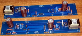
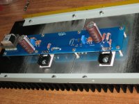
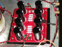
OK DIY folks another Update
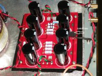
The Last of the components arrived yesterday and have been fitted
We used Caddocks for the input shunt resistors and Vishay Z foils for the input series resistor.
Chose this combo of resistor brands because that's what was available at time of ordering
Photos will show
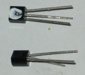
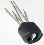
Smear of heat-sink grease on the input jfets before being coupled with
heat-shrink
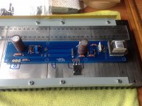
Also the finished assembly of the PGBs.
FR
The Last of the components arrived yesterday and have been fitted
We used Caddocks for the input shunt resistors and Vishay Z foils for the input series resistor.
Chose this combo of resistor brands because that's what was available at time of ordering
Photos will show
Smear of heat-sink grease on the input jfets before being coupled with
heat-shrink
Also the finished assembly of the PGBs.
FR
Attachments

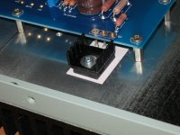
The next update on this thread for DIYers that a following
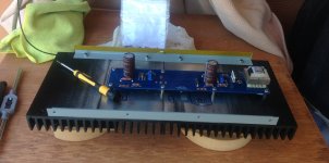
Previously I noted that the PCBs are complete with only the transistors to be done after possiioning and attaching the boards to the heat sink
For accuracy I used a hand drill press unit, I actually screwed the press unit onto a timber base for rigidity and levelled off the heat sink before driling the holes in
Then all holes were thread tapped with M3 X 0.5 pitch
I have elected to use Stainless Steel standoffs over brass
Mock up assembly was next
Afterwards all components were cleaned and fitted securely
Next update will be of the new wiring, removal of the soft start unit and tweaks inside the case
FR
Attachments
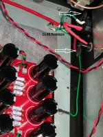
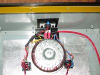
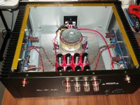
Sorry for the delay
In these photos you will see that the soft start module has been removed and a new power supply wire fitted
The soft start replacement system with the CL60 Resistors
FR
In these photos you will see that the soft start module has been removed and a new power supply wire fitted
The soft start replacement system with the CL60 Resistors
FR
Attachments
Last edited:
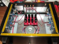
All new wiring is neat and tidy in its most simplistic way
Next installment will be measurements and listening reports
FR
Next installment will be measurements and listening reports
FR
Attachments
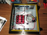
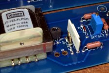
Bios and adjustments
At first we got no readings but we soon worked it out start turning the micro thread zenners
At first setting both channels have stabilized at damn near identical measurements.
bias left 497mv
bias right 496mv
Offset left and right under 1mv.
heatsink temp left 47.4
heatsink temp right 46.7
The right heatsink faces the door and there's a tiny bit of air movement.
So we guess that accounts for the marginal temp difference between channels.
ambient temp 27.7
temp delta left +19.7
temp delta right +19.0
Glad to be rid of that old soft start because it used to have a little buzz.
Now its beautiful silence
did you apply correction to the board as mention here?
http://www.diyaudio.com/forums/pass-labs/216616-f6-amplifier-155.html#post4518022
http://www.diyaudio.com/forums/pass-labs/216616-f6-amplifier-155.html#post4518022
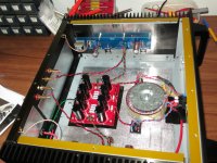
Nice! What's that foil at the back and the bottom?
That is a sheet of self adhesive silver foil lined soundproofing material
FR
did you apply correction to the board as mention here?
http://www.diyaudio.com/forums/pass-labs/216616-f6-amplifier-155.html#post4518022
we did some changes to the Zener and capacitors to make it more stable and easier to adjust the bios
This is the modified schematic we used & it was released earlier in this thread
But thanks for the link, I will have a read
FR
Attachments

- Status
- Not open for further replies.
- Home
- Amplifiers
- Pass Labs
- Upgrade F5 to F6