Do you understand what the parts of the Tubes are?
The reason I ask is the output tube..the one connected to the output transformer.
If we number the tubes from left to right V1, V2, V3 <<the output tube.
What voltage do you have across the cathode resistor on V3? And what value is the resistor?
Can you also list the tube numbers/types V1 is ........V2 is .......V3 Is .....
Also a question where did the circuit come from because the output transformer connection is rather strange..Like an attempt at PP using SE..
Take a look here..
https://www.google.co.uk/search?q=s...urm1ZC4yAIVAs8aCh21xgHh#imgrc=RGO5CncWPaq21M:
Now compare your output transformer connections.. B+ would be your 12V in this instance.
So the first thing you need to do is get the output tube V3 in conduction (working) you need a voltage across the cathode resistor.
If you don't know which is the cathode resistor on the link its the 470 Ohm 25W. compare to your circuit.
Also on the linked diagram the UL 43% is the screen grid and the connection on your diagram would appear to be wrong unless you know for sure that this is the correct connection..which would be strange.
Regards
M. Gregg
The reason I ask is the output tube..the one connected to the output transformer.
If we number the tubes from left to right V1, V2, V3 <<the output tube.
What voltage do you have across the cathode resistor on V3? And what value is the resistor?
Can you also list the tube numbers/types V1 is ........V2 is .......V3 Is .....
Also a question where did the circuit come from because the output transformer connection is rather strange..Like an attempt at PP using SE..
Take a look here..
https://www.google.co.uk/search?q=s...urm1ZC4yAIVAs8aCh21xgHh#imgrc=RGO5CncWPaq21M:
Now compare your output transformer connections..
B+ would be your 12V in this instance.So the first thing you need to do is get the output tube V3 in conduction (working) you need a voltage across the cathode resistor.
If you don't know which is the cathode resistor on the link its the 470 Ohm 25W. compare to your circuit.
Also on the linked diagram the UL 43% is the screen grid and the connection on your diagram would appear to be wrong unless you know for sure that this is the correct connection..which would be strange.
Regards
M. Gregg
Last edited:
The reason I ask is the output tube..the one connected to the output transformer.
The circuit shown is correct for operation with "space charge" tubes. These are a special type of tube designed for operation directly from a 12 volt car battery. Max plate voltage is 30 volts.
In normal operation the output tube tetrode has G1 tied to B+ and G2 is the signal grid which uses grid leak bias (usually 1 to 3 megohms). The cathode is usually tied directly to ground.
There are dozens of circuits on the web where small low powered (100 to 500 MILLIWATS) guitar amps have been built with these tubes. Google "space charge guitar amp." Positive feedback to G1 could slightly increase power output and increase distortion.
The issue with this design is that the 12DU7 is a conventional 12 volt tube. G1 is the signal grid, and G2 gets 12 volts. To make a 12DU7 work in this circuit, the G1 and G2 connections need to be swapped. The cathode resistor must be a small value.
I do not know if the Russian tubes chosen for the preamp will work on 12 volts, since I have never used them. The common 12 volt guitar preamp tube is the 12U7, although some have made 12AU7's work on 12 volts.
yes, i have swapped this around as i realized that they were backwards for this tube and followed everything stated and with no luck. i know 100% it is to do with the OPT or the output tube wiring. this is very frustrating but getting closer to solving it with the help from you guys. also i think i fried the resistor that ties the preamp output to the power tube input as when i put my MM on it i get 0 reading.
Aran
Aran
The circuit shown is correct for operation with "space charge" tubes. These are a special type of tube designed for operation directly from a 12 volt car battery. Max plate voltage is 30 volts.
In normal operation the output tube tetrode has G1 tied to B+ and G2 is the signal grid which uses grid leak bias (usually 1 to 3 megohms). The cathode is usually tied directly to ground.
Is this similar to the 12K5?
Ie connected like this?
http://www.sophtamps.ca/schematics/sopht-12k5-30v-v5.jpg
Regards
M. Gregg
yes, i have swapped this around as i realized that they were backwards for this tube and followed everything stated and with no luck. i know 100% it is to do with the OPT or the output tube wiring. this is very frustrating but getting closer to solving it with the help from you guys. also i think i fried the resistor that ties the preamp output to the power tube input as when i put my MM on it i get 0 reading.
Aran
What voltage do you have across the cathode resistor of the 12du7?
You need to be systematic so forget the preamp at the moment.
Regards
M. Gregg
i haven't grounded the anode. your reply to this 'please tell me you are kidding'
Aran
No don't ground the anode...
Ok wait a moment..
Regards
M. Gregg
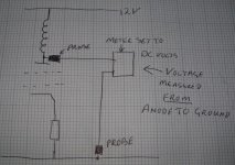
Voltage measurement,
Anode to ground..
All measurements through the meter from one point to another..
If you click on the picture it makes it bigger..
Then..
Cathode resistor voltage from cathode to Ground using the meter set to DC volts.
Don't short anything out ever..LOL
Regards
M. Gregg
Anode to ground..
All measurements through the meter from one point to another..
If you click on the picture it makes it bigger..
Then..
Cathode resistor voltage from cathode to Ground using the meter set to DC volts.
Don't short anything out ever..LOL
Regards
M. Gregg
Attachments
Last edited:
ok i got a reading of 12v
Ok what voltage from the cathode to ground across the cathode resistor.
Regards
M. Gregg
0 volts..
This is where the problem is at the moment..
The tube is not conducting.
Either the cathode resistor is open circuit or the connection on the output transformer is wrong.
SO POWER OFF
and check the cathode resistor to see if it's OK.
Then post what you find..is the cathode resistor OK?
Remember to put your meter back to DC volts after you do this..
Regards
M. Gregg
Aran,
The 330 ohm could be to high in value, however try connecting the tube as shown for the 12K5 and leave the resistor as is to start with and see if we get a voltage across the cathode resistor then we can take it from there.
I have to sign off for a while I'll get back as soon as I can.
Regards
M. Gregg
- Status
- This old topic is closed. If you want to reopen this topic, contact a moderator using the "Report Post" button.
- Home
- Amplifiers
- Tubes / Valves
- wiring tubes in series