Hi Terry,
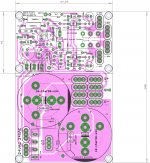
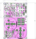
I used eagle. (most people on the forum seem to hate the poor program😀😀!). However pl find the file in the attached folder. Also png images with 600dpi
Happy building!!
Regards
Prasi
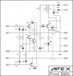
Nice pcb... you can add another 560R/2W in parallel with 560R/2W on pcb. You will need 4W with higher rail voltage. This stereo protect can be use with any other amp like AX14, NX14...
Regards
Nice pcb... you can add another 560R/2W in parallel with 560R/2W on pcb. You will need 4W with higher rail voltage. This stereo protect can be use with any other amp like AX14, NX14...
Regards
Done Mr. Mile,
attached below.
reg
prasi
PS Also made provision for 22.5mm LS-4 pin caps for PSU.
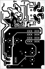
I seem to be having trouble converting the layout to pdf. I searched internet and it seems eagle has trouble converting polygons (straight edge lines appear inside polygons).
Attachments
Last edited:
see attached- funny, lots of people have commented and still there is no solution from cadsoft!!
How are you converting them to PDF? I use Foxit Reader. "Print" your file using Foxit PDF printer instead of your usual printer. The output is saved as a PDF.
well I tried inbuilt pdf save option, MS XPS print to file option, cutepdf creator. same results. I am downloading foxit as i type .
reg
prasi
reg
prasi
There is also bullzip.
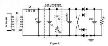
Also in your design, you have no emi suppression ( for diode switch off) nor snubbers R/C(switch off ringing). So it can be improved. Take a look at the Quasimodo thread and the app note on this subject for more info.
Also in your design, you have no emi suppression ( for diode switch off) nor snubbers R/C(switch off ringing). So it can be improved. Take a look at the Quasimodo thread and the app note on this subject for more info.
Last edited:

There is also bullzip.
Also in your design, you have no emi suppression ( for diode switch off) nor snubbers R/C(switch off ringing). So it can be improved. Take a look at the Quasimodo thread and the app note on this subject for more info.
are you suggesting this ckt? CRC snubber? that can be done.
I would like to know
1.how to incorporate back emf diode on relay
Attachments
Sorry to report jeff, but no improvement. Guess its a problem with eagle.
reg
prasi
I couldn't get the point.
Would this attachment help?
Attachments
did you convert the png image into pdf?

Yes, using Corel Draw. Is that what you need?
Otherwise, I will remove the post.
Take a look at figure 13, center tapped secondary for wiring of the Cx,Cs/Rs. Left fig is your ckt, on the right is how you connect to Quasimodo for testing your transformer.
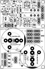
Rs needs to be determined by using Quasimodo to figure out the optimal damping for your particular transformer. But you can try or place Cs=10n, Cs = 150n, Rs = 22-100ohm on your pcb for this feature.
The relay back emf diode is always reversed biased, so that it conducts when the relay is switched off.
Take a look at figure 13, center tapped secondary for wiring of the Cx,Cs/Rs. Left fig is your ckt, on the right is how you connect to Quasimodo for testing your transformer.
Rs needs to be determined by using Quasimodo to figure out the optimal damping for your particular transformer. But you can try or place Cs=10n, Cs = 150n, Rs = 22-100ohm on your pcb for this feature.
The relay back emf diode is always reversed biased, so that it conducts when the relay is switched off.
Hi Rsavas,
Added, pl see attached. One has to experimentally determine the value of R16/R17, nominal values as per your suggestion given. Question: What is the power dissipated thro the res., because resistors are responsible for damping.
To: Mr. Mile,
Thanks for the updated schematic, incorporated in the layout. Question: How can the overcurrent detector of this protect be used for circuits without emitter resistor?(e.g. PEECEEBEE having latfets)
reg
Prasi
Attachments
got the answer for the Power dissipated.
For 75V RMS secondary 60 to 70 mW. Since the voltage here is quite low, I guess quarter watt resistors would be just fine.
reg
prasi
For 75V RMS secondary 60 to 70 mW. Since the voltage here is quite low, I guess quarter watt resistors would be just fine.
reg
prasi
Looks good!!
Question: How can the overcurrent detector of this protect be used for circuits without emitter resistor?(e.g. PEECEEBEE having latfets)
One way or the other you have to sense the current and then set up some sort of threshold detection, level shifting if sensing the high side. That or a high side fuse 🙂 if one of the fuses blows, I guess the o/p will hit a rail then the DC detect will trigger the relay.
- Home
- Amplifiers
- Solid State
- 100W Ultimate Fidelity Amplifier