Whose experiment? Whose terms?
The method of observation changes the experiment -- the Zin of the AP2722 is 100k, the load in Scott's experiments is 1Meg so you've reduced the Zout to 90.9k. QED.
The BF862 JFET front end is a wonderful device which won't load the DUT. I use a HV polypro cap which, after connecting to the tube, is discharged. This puts minimal load on the DUT.
Thanks. Yes, I love 862s, and we're likely to have them around for a while, as I understand they are used in large quantities in Chinese AM radios. If cascoded, especially, as they do have fairly low breakdown voltages.The method of observation changes the experiment -- the Zin of the AP2722 is 100k, the load in Scott's experiments is 1Meg so you've reduced the Zout to 90.9k. QED.
The BF862 JFET front end is a wonderful device which won't load the DUT. I use a HV polypro cap which, after connecting to the tube, is discharged. This puts minimal load on the DUT.
A buffer would be nice, but I have now accounted for the 100k loading (see recent post).
The specific tube has a plate resistance for grounded cathode of about 1.8k, so the loading by the Ap is correspondingly less significant. Nonetheless, it can be included. I'm not essaying to replicate the previous devices' results, just characterize a few samples of the C45. As I may have mentioned I came to the thread here after taking the data I presented.
There are cases where the 100k is a lot, and a buffer would be mandatory. I presented an example, in another thread, of one using a 2SK389 as a follower with bootstrapped cascode higher Vp FETs, in order to see what the effect of driving the substrate was for rather high source resistances (~100k was tested) on distortion. Turned out it was appreciable. Of course with no substrate there's no problem 🙂
FWIW, I think the whole test procedure here is somewhat flawed. If you are
trying to measure very low levels of noise, especially in very high gm frame
grid tubes, their self noise can easily be well below that of a 390 ohm
input resistor.
Noise figure is not a very useful specification when it comes to noise.
Input referred noise in nV/rt Hz versus frequency (with a shorted input) is
far more useful. If I see nV/rt Hz and in the case of a BJT current noise in
pA/rt Hz I immediately know what I am dealing with and how it will work in a
given situation.
cheers
Terry
Hi Terry,
From a circuit designer’s perspective, I agree that it would be better to have Ein and Iin evaluated over frequency for each tube brand and type. But because those voltage and current noise spectral densities do vary greatly, both over frequency and from tube-to-tube, it would be extremely time consuming for me to make those measurements for a hundred tubes. To my knowledge, that information is simply not available for tubes, as it is for transistors, and it frustrated me.
Therefore, I decided to simplify the problem and yet still provide some practical data available nowhere else. My measurements are providing input-referred noise, integrated over an 8kHz bandwidth. Anyone who wants to can subtract off the noise power attributable to the 390 ohm input resistor and come up with Ein.
Like you, I started this project believing that high-transconductance, frame-grid RF tubes would provide much lower noise than audio tubes, but so far it does not appear to be true. At audio frequencies, noise appears to be dominated by other mechanisms, such as 1/f noise. I was disappointed to discover that current production tubes like the Electro-Harmonix (Reflektor) 6922 and the JJ E88CC provide the same or high noise than 12AX7s.
I am looking forward to trying out some of the more exotic tubes (6n16, 6c45, 6CW4) suggested by contributors to this forum. If we do discover tubes that approach the noise levels of the 390 ohm resistor, I can reduce the value of the grid resistor and make other more detailed measurements, as justified. But so far, even the lowest noise tube measured (the D3a), has ~5.2dB higher noise over an 8kHz BW than the 390 ohm resistor, and I’ve sanity-checked those results by shorting out the 390 ohm resistor and observing the degree of reduction in noise.
Scott
I think you have done a great job with the tools available. And the strategy of going from 390 ohms to 0 ohms is one of many reality checks.Hi Terry,
From a circuit designer’s perspective, I agree that it would be better to have Ein and Iin evaluated over frequency for each tube brand and type. But because those voltage and current noise spectral densities do vary greatly, both over frequency and from tube-to-tube, it would be extremely time consuming for me to make those measurements for a hundred tubes. To my knowledge, that information is simply not available for tubes, as it is for transistors, and it frustrated me.
Therefore, I decided to simplify the problem and yet still provide some practical data available nowhere else. My measurements are providing input-referred noise, integrated over an 8kHz bandwidth. Anyone who wants to can subtract off the noise power attributable to the 390 ohm input resistor and come up with Ein.
Like you, I started this project believing that high-transconductance, frame-grid RF tubes would provide much lower noise than audio tubes, but so far it does not appear to be true. At audio frequencies, noise appears to be dominated by other mechanisms, such as 1/f noise. I was disappointed to discover that current production tubes like the Electro-Harmonix (Reflektor) 6922 and the JJ E88CC provide the same or high noise than 12AX7s.
I am looking forward to trying out some of the more exotic tubes (6n16, 6c45, 6CW4) suggested by contributors to this forum. If we do discover tubes that approach the noise levels of the 390 ohm resistor, I can reduce the value of the grid resistor and make other more detailed measurements, as justified. But so far, even the lowest noise tube measured (the D3a), has ~5.2dB higher noise over an 8kHz BW than the 390 ohm resistor, and I’ve sanity-checked those results by shorting out the 390 ohm resistor and observing the degree of reduction in noise.
Scott
WRT Noise -- the ear's sensitivity to noise rises with frequency, peaking around 6kHz. Dolby found that the best correlation to human experience of noise was (now ITU) CCIR-486 with average measurement (not quasi-peak).
6C45 sample-to-sample parameter variations
Got these C45 Amplitrex data from the friend, in turn sent by a vendor after being asked to match some. As suggested by someone earlier, good luck paralleling five of them! Or even two.
Transconductance numbers are in uS; curious notation for milliamperes. I would prefer a constant current be provided rather than a constant plate voltage, but so it goes.
Plate Voltage = 75V
Plate Current= 10 m/A
Bias Voltage = Auto-Bias
Tube #1:
PC= 10.1 m/A
GM= 18400
Bias Voltage= 0.8
Mu= 38.6
Tube #2:
PC= 9.7 m/A
GM= 21600
Bias Voltage = 0.4
Mu= 45.3
Tube #3:
PC= 10.2 m/A
GM= 19530
Bias Voltage= 0.7
Mu=42.9
Tube #4:
PC=9.6 m/A
GM=23970
Bias Voltage= 0.1
Mu= 40.7
Tube #5:
PC=11.9 m/A
GM=23000
Bias Voltage= 0.0
Mu= 46.2
Tube #6:
PC=9.6 m/A
GM=19800
Bias Voltage= 0.3
Mu=43.5
Tube #7:
PC=12.0 m/A
GM=22500
Bias Voltage=0.3
Mu=40.5
Tube #8:
PC=10.1 m/A
GM=17600
Bias Voltage=0.3
Mu=44.0
Tube #9:
PC=9.9 m/A
GM=23000
Bias Voltage=0.8
Mu=43.7
Tube #10:
PC=10.8 m/A
GM=22160
Bias Voltage=0.6
Mu=42.1
Tube #11:
PC=9.6 m/A
GM=22250
Bias Voltage=0.7
Mu=60.0
Tube #12:
PC=9.8 m/A
GM=24460
Bias Voltage = 0.0
Mu=41.5
Hi,
That's exactly the problem with valves having extreme specs like that.
The only way to use them in parallel is to provide for individual negative bias etc so that only the grids are effectively in //. And then some..........
Thanks again Brad, 😉
That's exactly the problem with valves having extreme specs like that.
The only way to use them in parallel is to provide for individual negative bias etc so that only the grids are effectively in //. And then some..........
Thanks again Brad, 😉
Transconductance numbers are in uS; curious notation for milliamperes. I would prefer a constant current be provided rather than a constant plate voltage, but so it goes.
Transconductance (gm) is measured in milliamperes per volt which is an admittance. The units of admittance are Siemens. gm is defined as the change in plate current with respect to grid voltage at a constant plate voltage.
https://en.wikipedia.org/wiki/Admittance
Cheers
Ian
I may have paired my remark about operating the DUTs with a constant current, being something I would prefer, too close in proximity to the one about the Amplitrex presentation of data. The Amplitrex transconductances are shown in microsiemens, i.e. microamperes per volt, not millisiemens, which is not uncommon for hollow state specs.Transconductance (gm) is measured in milliamperes per volt which is an admittance. The units of admittance are Siemens. gm is defined as the change in plate current with respect to grid voltage at a constant plate voltage.
https://en.wikipedia.org/wiki/Admittance
Cheers
Ian
For the data I took on the 6C45's I operated the samples at a 10mA constant plate current, zero d.c. bias on the grid (other that the offset from the grid current flowing in the external voltage divider) and zero volts on the cathode. The loading on the plate was the Ap input of 100k, although as pointed out by another, a higher-Z buffer could make the loading effect much less. The plate voltage was allowed to assume whatever voltage it went to, typically 62 to 72V quiescent.
Then, when the generator drove the voltage divider, level and distortion measurements, and spectra of the latter, were obtained. Output noise was measured with the generator off. When driven, the plate voltages represented the grid voltage change times the transconductance (thus a current signal) times the parallel value of plate resistance and the 100k Ap input. If the Ap loading were removed and the current source ideal (zero output conductance) the magnitude of the voltage gain from grid to plate would be precisely mu, that is, gm * Rp. These two terms can be determined independently by getting additional data with a heavier a.c. load on the plate. When I did that with a 1.50k resistor in series with a 10uF capacitor to common and measured the resulting reduced gain, I was able to extract the gm and Rp for a given sample. The result for one was 28.3mS and 1.80k, hence a mu of 51.
Since the signals at the plate were still small and centered around the quiescent plate voltage, the derived parameters are still close to the conventional definitions for constant plate voltage. They are appropriate for the envisioned use as a stepup stage.
It's interesting that the three samples I tested had mu quite close to that number of 51, while the plate voltages had substantially more variation. But the statistics from three samples is likely poor. I'm done with the investigation for now.
I cranked through the maths to get Rp, gm, and their product mu for the other two tubes I tested.
Rp = 1.71k, gm = 29.2mA/V, mu 49.9; another was Rp = 1.93k, gm = 27.2mA/V, mu = 52.5. As mentioned the plate voltages vary for the 10mA constant current.
With only three samples it is risky to conjecture, but it may be that the constant current operation has advantages for combining the outputs of more than one tube, to reduce noise. OTOH simple paralleling seems a bad bet.
WRT Noise -- the ear's sensitivity to noise rises with frequency, peaking around 6kHz. Dolby found that the best correlation to human experience of noise was (now ITU) CCIR-486 with average measurement (not quasi-peak).
Hi Jack,
Good point. And the ear’s sensitivity falls sharply beyond 8kHz.
If you happen to be selecting low noise tubes for use in a phono stage, it is interesting to consider the additional effect of RIAA weighting. The RIAA playback curve essentially falls at 6dB/octave over the audio band (with a 2 octave flat region from 500 – 2000 Hz), which almost exactly cancels out the ITU-R 468 curve up to 6kHz!! To the extent that the ITU curve represents the actual sensitivity of human hearing, it means that tube noise in a phono stage would be perceived equally at all frequencies up to 6kHz. Beyond that, both the ITU curve and the RIAA curve fall sharply and tube noise would not be perceived.
Indeed, if I turn up the volume to max with no LP playing, the noise is more of a “rush” than a “hiss”.
Scott
Well I said I was done, but I'm finding other chores oddly unappealing. One would think it was tax preparation season!I cranked through the maths to get Rp, gm, and their product mu for the other two tubes I tested.
Rp = 1.71k, gm = 29.2mA/V, mu 49.9; another was Rp = 1.93k, gm = 27.2mA/V, mu = 52.5. As mentioned the plate voltages vary for the 10mA constant current.
With only three samples it is risky to conjecture, but it may be that the constant current operation has advantages for combining the outputs of more than one tube, to reduce noise. OTOH simple paralleling seems a bad bet.
I measured four more C45s and am strengthing my conjecture that operating them at a constant quiescent current (in this case 10mA) and fixed (in this case zero) grid and cathode voltage is advantageous for reducing the spread of mu. In fact, so much better that it calls into question some of the Amplitrex data, taken by my friend's tube vendor, which are based on a constant plate voltage (75V) and adjusting the grid bias to get the 10mA. I'll measure a few more (four left, one of which may be defective) and get some statistics out of the lot.
Now since any sand is anathema to many, and tube I sources are somewhat cumbersome, what might work as a quasi-paralleling strategy would be to adjust individual plate voltages by placing a voltage drop, maybe from a well-bypassed resistor, in series with the tube(s) requiring a lower plate voltage. As electrolytics are also often shunned, perhaps a big film cap across the given resistor. I'm not sure if the optimization should be for equal mu or equal plate currents, as far as the impact on noise and distortion.
A lot of trouble and a lot of labor to be sure, and a bulky assembly. But the numbers I'm getting are a lot less pessimistic than the tube vendor's Amplitrex data.
Yes, less objectionable to most, even if the measurements don't look so good.Indeed, if I turn up the volume to max with no LP playing, the noise is more of a “rush” than a “hiss”.
Scott
Some hot-shot landline tubes like the E180F were spec'd with a big cathode resistor (bypassed, of course) and a positive 9 volts or so grid voltage. They seem to agree with you about variability, even in the Golden Age.
Thanks, as always,
Chris
Thanks, as always,
Chris
Statistics for 10 pieces of the 6C45
Operated at 10mA Ip and zero d.c. on cathode and grid:
Rp mean 1.796k, standard deviation 147.8 ohms
gm mean 27.04mA/V, s.d. 1.378mA/V
mu mean 47.866, s.d. 2.902.
Without cranking through the Amplitrex data supplied by the tube vendor, glancing over them I think it's still safe to say that my ten samples have a tighter distribution of these parameters. Whether this is luck of the draw or something about the way these tubes work is open to conjecture. I'm not going to spend 300 bucks to find out.
Noise referred to the input ranged from 2.5nV/sq rt Hz to about 1.8nV/sq rt Hz in a 400Hz - 22kHz bandwidth.
As far as combining tube outputs, it seems plausible to adjust the plate voltages with some voltage drop in series with a given plate. This would work better for the friend's app as he wants to have the plate(s) loaded with a transformer. The loading on the secondary of the transformer I guess would be just the input of the MM preamp, with the turns ratio adjusted to give the desired stepup gain. If the latter is 20dB, the turns ratio would be about 4.8:1 and the transformed plate loads quite high, although some additional termination a la Zobel to control peaking would likely be required on the secondary.
All in all, even the ~2nV/sq rt Hz may be acceptable for a lot of MC cartridges.
Hi Everyone,
I updated the list of measurements on our website. It now includes measurements on the Toshiba 2SK209 low-noise audio JFET, the RU-6C45PI (suggested by bcarso), and RU-6H6 (suggested and sent to me by Koifarm – thanks!).
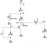
The 2SK209 JFET is an interesting comparison to all the tubes, and it also provides a sanity check on my measurements. I’ve attached the test circuit. The 52 volt power supply is provided by six 9-v batteries in series, to avoid any powerline harmonics. The 30 Hz – 8 kHz integrated input-referred noise of the 2SK209 was 0.253 µV RMS with the switch open and 0.142 µV with the switch closed. The 2SK209 NF referred to 390 Ω is ~0.9dB, much lower than any tube measured in this study.
The RU-6H6 is similar to the JJ ECC99 in terms of gain and noise performance.
The current production Sovtek RU-6C45PI has similar construction to the NOS Siemens D3a and also displays similar very low NF around 5dB (referred to 390 Ω). My noise data does not agree perfectly with what Brad has posted on this thread, possibly because of my 8kHz measurement BW (vs. Brad’s 20kHz BW). But we both agree that it is a very low noise tube.
The 6C45PI also has similar microphonic behavior to the D3a. Measured in the same way as for the D3a, there is a distinct vibrational mode at 3 kHz and a broad spectrum from 12 – 17 kHz. There are more minor modes at 800 Hz, 4.8 kHz, and 6.8 kHz. The mode at 3 kHz and the other minor modes damp out within a few seconds, but the spectrum from 12 – 17 kHz can persist for 30 seconds or more. Only two Sovtek 6C45PI have been measured, but both showed similar microphonic behavior. The 6C45PI and D3a tubes are much more microphonic than other audio tubes in this study.
Next up for measurement are the 6CW4 and the 6H16 Koifarm sent me.
Scott
I updated the list of measurements on our website. It now includes measurements on the Toshiba 2SK209 low-noise audio JFET, the RU-6C45PI (suggested by bcarso), and RU-6H6 (suggested and sent to me by Koifarm – thanks!).
The 2SK209 JFET is an interesting comparison to all the tubes, and it also provides a sanity check on my measurements. I’ve attached the test circuit. The 52 volt power supply is provided by six 9-v batteries in series, to avoid any powerline harmonics. The 30 Hz – 8 kHz integrated input-referred noise of the 2SK209 was 0.253 µV RMS with the switch open and 0.142 µV with the switch closed. The 2SK209 NF referred to 390 Ω is ~0.9dB, much lower than any tube measured in this study.
The RU-6H6 is similar to the JJ ECC99 in terms of gain and noise performance.
The current production Sovtek RU-6C45PI has similar construction to the NOS Siemens D3a and also displays similar very low NF around 5dB (referred to 390 Ω). My noise data does not agree perfectly with what Brad has posted on this thread, possibly because of my 8kHz measurement BW (vs. Brad’s 20kHz BW). But we both agree that it is a very low noise tube.
The 6C45PI also has similar microphonic behavior to the D3a. Measured in the same way as for the D3a, there is a distinct vibrational mode at 3 kHz and a broad spectrum from 12 – 17 kHz. There are more minor modes at 800 Hz, 4.8 kHz, and 6.8 kHz. The mode at 3 kHz and the other minor modes damp out within a few seconds, but the spectrum from 12 – 17 kHz can persist for 30 seconds or more. Only two Sovtek 6C45PI have been measured, but both showed similar microphonic behavior. The 6C45PI and D3a tubes are much more microphonic than other audio tubes in this study.
Next up for measurement are the 6CW4 and the 6H16 Koifarm sent me.
Scott
Attachments
Scott, did you double check that nothing was oscillating at VHF? That's often a source of microphonics, and those are two tubes which are notorious for believing that they are VHF generators.
Hi SY,
Yes, I did check. It was discussed on this thread back when I first posted measurements on the D3a, and I just re-checked the 6C45. I probed all internal nodes on the test circuits with a 10X RF probe and a 100MHz analog scope, which should detect any RF oscillation up to 150MHz or so. There is no RF output from the circuit, even when touching or tapping the tubes.
The only output from the test circuits (besides the noise) follows after touching or tapping the tubes, and only at audio frequencies (and low ultrasonic).
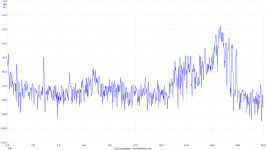
My test for microphonics is to tap gently with my finger on the aluminum box, wait ~0.3 seconds (basically my reaction time to click the mouse), then capture the spectrum of the microphonics. You can see the spectra for the 6C45 and D3a compared in the summary on the website. I think the sharp peaks around 3kHz may be hi-Q mechanical resonance in the structure. Not sure how else to explain it. Fascinating.
What seems to be unique about the D3a and 6C45 is the persistence of the microphonics. All tubes are microphonic, but the spectra of other tubes in the study faded away much too quickly to capture by this method.
Best,
Scott
Yes, I did check. It was discussed on this thread back when I first posted measurements on the D3a, and I just re-checked the 6C45. I probed all internal nodes on the test circuits with a 10X RF probe and a 100MHz analog scope, which should detect any RF oscillation up to 150MHz or so. There is no RF output from the circuit, even when touching or tapping the tubes.
The only output from the test circuits (besides the noise) follows after touching or tapping the tubes, and only at audio frequencies (and low ultrasonic).
My test for microphonics is to tap gently with my finger on the aluminum box, wait ~0.3 seconds (basically my reaction time to click the mouse), then capture the spectrum of the microphonics. You can see the spectra for the 6C45 and D3a compared in the summary on the website. I think the sharp peaks around 3kHz may be hi-Q mechanical resonance in the structure. Not sure how else to explain it. Fascinating.
What seems to be unique about the D3a and 6C45 is the persistence of the microphonics. All tubes are microphonic, but the spectra of other tubes in the study faded away much too quickly to capture by this method.
Best,
Scott
Interesting- I just don't get that sort of level of microphonics from the D3a I have on hand. Except when it was pretending to be a TV transmitter, and yes, it will absolutely be modulated by mechanical resonances as you observed.
I have an idea for a microphonics test that I'll try out as soon as I get the last measurements knocked out for a different project.
I have an idea for a microphonics test that I'll try out as soon as I get the last measurements knocked out for a different project.
I followed -45 ringing on the scope down into the noise level, and it took many seconds. Whatever part of the structure accounts for the resonance, the hyper-close grid-cathode spacing surely exacerbates the effect. Sadly, as noted, the frequency is well within the audio band.Interesting- I just don't get that sort of level of microphonics from the D3a I have on hand. Except when it was pretending to be a TV transmitter, and yes, it will absolutely be modulated by mechanical resonances as you observed.
I have an idea for a microphonics test that I'll try out as soon as I get the last measurements knocked out for a different project.
What was also interesting to note was the electrical output from excitations when I changed heater power in "real time".
- Home
- Amplifiers
- Tubes / Valves
- List of Tube Noise Measurements - please nominate lowest noise tubes