Note that the maximum voltage swing with an inductor or transformer exceeds the supply voltage and is almost twice B+. This is because the inductor/Transformer stores energy in it's magnetic field and re-releases it inducing a voltage which adds to the supply voltage.
I read the article jazbo recommended, but that is for a single-ended triode. That part I'm pretty sure I understand. The problem is figuring a push-pull loadline without cutting and pasting together two sets of characteristic curves to create a composite loadline.
I've read several articles on how to do that, such as http://www.ax84.com/media/ax84_m225.pdf and The Valve Wizard -Push-Pull.
I only want to figure a loadline for a pair of triodes in class A. I'll get to pentodes and class AB later.
According to the ax84 pdf, I think I figured it right. But I'm not sure. I think it says to figure the push-pull loadline by using a load resistance that is 1/4 the plate-to-plate impedance of the transformer to be used. Then find the 'slope' of the loadline by using a much lower B+ voltage, and finding the intersection on the Y axis. Now move that 'slope' out to where it intersects with the desired operating point.
Or (as the Valve Wizard article implies) should I use 1/2 the p-p impedance for class A, and 1/4 the p-p impedance for class AB?
--
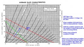
If I take that loadline I drew for 10k p-p with B+ of 200V, and move the slope of that loadline to the right along the X axis to where it meets a B+ of 400V, I get a plausible looking operating point.
Using that method, I find that using a 5k p-p OPT with 6L6 triodes, I get a very vertical looking loadline. Bump that up to 10k p-p, and it starts looking usable. That seems like it would fit with real life results.
Am I completely off-base here?
--
I've read several articles on how to do that, such as http://www.ax84.com/media/ax84_m225.pdf and The Valve Wizard -Push-Pull.
I only want to figure a loadline for a pair of triodes in class A. I'll get to pentodes and class AB later.
According to the ax84 pdf, I think I figured it right. But I'm not sure. I think it says to figure the push-pull loadline by using a load resistance that is 1/4 the plate-to-plate impedance of the transformer to be used. Then find the 'slope' of the loadline by using a much lower B+ voltage, and finding the intersection on the Y axis. Now move that 'slope' out to where it intersects with the desired operating point.
Or (as the Valve Wizard article implies) should I use 1/2 the p-p impedance for class A, and 1/4 the p-p impedance for class AB?
--
If I take that loadline I drew for 10k p-p with B+ of 200V, and move the slope of that loadline to the right along the X axis to where it meets a B+ of 400V, I get a plausible looking operating point.
Using that method, I find that using a 5k p-p OPT with 6L6 triodes, I get a very vertical looking loadline. Bump that up to 10k p-p, and it starts looking usable. That seems like it would fit with real life results.
Am I completely off-base here?
--
Last edited:
Your on the right track.....I read the article jazbo recommended, but that is for a single-ended triode. That part I'm pretty sure I understand. The problem is figuring a push-pull loadline without cutting and pasting together two sets of characteristic curves to create a composite loadline.
I've read several articles on how to do that, such as http://www.ax84.com/media/ax84_m225.pdf and The Valve Wizard -Push-Pull.
I only want to figure a loadline for a pair of triodes in class A. I'll get to pentodes and class AB later.
According to the ax84 pdf, I think I figured it right. But I'm not sure. I think it says to figure the push-pull loadline by using a load resistance that is 1/4 the plate-to-plate impedance of the transformer to be used. Then find the 'slope' of the loadline by using a much lower B+ voltage, and finding the intersection on the Y axis. Now move that 'slope' out to where it intersects with the desired operating point.
Or (as the Valve Wizard article implies) should I use 1/2 the p-p impedance for class A, and 1/4 the p-p impedance for class AB?
--
If I take that loadline I drew for 10k p-p with B+ of 200V, and move the slope of that loadline to the right along the X axis to where it meets a B+ of 400V, I get a plausible looking operating point.
Using that method, I find that using a 5k p-p OPT with 6L6 triodes, I get a very vertical looking loadline. Bump that up to 10k p-p, and it starts looking usable. That seems like it would fit with real life results.
Am I completely off-base here?
--
Technically many "load-Lines" will fit and work...but the key question is how to achieve an OPTIMUM plate load.... This is defined in Hi-Fi applications as the plate load that will give you the best bang for the buck.... a balance between Power Output/efficiency and Distortion.. Well Efficiency was the Marketing guys idea 🙂
Don't forget frequency response, If your plate load gets way too big you may have issue with winding capacitance now being a problem, but triodes generally work better into higher capacitance then pentodes due to the lower plate resistance and also better damping, to keep the Q from getting to peaky.. So what is really needed for the triodes is a low leakage transformer because of this...
Attached below is a situation where someone wanted to know the outcome of using a 4K Push-Pull Plate load with Tetrode mode ..... The quiescent voltages of 450V was not used, but rather the droop voltages that occurred at full power output are used... Keep in mind of 1K screen resistors are installed and responsible for additional Screen voltage droop.... The quick and dirty analysis was in perfect agreement with the amp's measured RMS power output ..... The tubes were very well matched and perfect gm to data sheet.... I did the verification testing of the 6L6 tubes on my 570 to be sure..
The RED line running vertical to the 450V is the IDLE line....meaning that you could bias anywhere you want along that vertical line, provided you don't melt the tubes.., since it is quiescent current draw the B+ supply will return to 450V...but under full power output condition where the B+ is at 425 for load-line analysis..
Textbooks typically show the idle current above the end of load-line, due to having an ideal power supply with no droop...
Biasing too cold towards cut-off makes for some nice cross-over notch due to the cut-off characteristics having a great reduction in gm at that area... I typically bias just a tiny bit past where the notch vanishes...for the most part..any hotter biasing is diminished returns...You can also use a distorion analyzer to bias... If the notch won't go away, then there are other issues, such as a bad tube with bad grid alignment, gassy grid or too much leakage in the transformer..
Attachments
Last edited:
Attached is Class-AB1 Push-Pull TRIODE tubes as you sugested...
Using KT88 tubes in TRIODE connected....
The Plate load comes out to 5K .....
The way the Plate load is figured for max output....
Choose the B+ as in this case 450V .... Then run the Load-Line tangential to the MAX Plate Dissipation curve..no curve but instead look for the small red stars, these are the "keep out zone" markers...
This is in consideration of a 40W plate dissipation....
The actual avg Plate Dissipation over the full Class-A cycle will be below the 40W if you calculate it....
When running more into CLASS AB then into B.... the avg cycle plate dissipation is reduced, thus the load-line can extend steeper.....
But then again, distortion analysis may indicate too much harmonics at 5K Plate load... May need to increase plate load value, thus sacrificing power output wattage for linearity....
You decide how you want to balance your trade-offs...
Attachments
Last edited:
I read the article jazbo recommended, but that is for a single-ended triode. That part I'm pretty sure I understand. The problem is figuring a push-pull loadline without cutting and pasting together two sets of characteristic curves to create a composite loadline.
You need to finish reading all 5 articles from Bench, the link was just the first one...😉
I only want to figure a loadline for a pair of triodes in class A. I'll get to pentodes and class AB later.
...
Or (as the Valve Wizard article implies) should I use 1/2 the p-p impedance for class A, and 1/4 the p-p impedance for class AB?
Your post #19 almost nails it, except for class A, you use 1/2 of the OPT Zpp, not 1/4.
For Class A, draw the loadline as 1/2 of the Zpp impedance, starting from the B+ and shift upwards until you reach the bias point where plate dissipation is as much as you allow the tube to run, usually it's 70-80% max plate dissipation.
For Class B, draw the loadline as 1/4 of Zpp impedance, starting from the B+. Since it's class B, your bias point is exactly at the loadline where it crosses B+ and 0mA.
For Class AB, draw both the 1/4 Zpp and 1/2 Zpp , starting from the B+ and you shift the 1/2 Zpp loadline upwards until you reach your target bias point. The higher the bias point, the more you stay in class A before shifting to class B. Valvewizard link explains it so much better.
Attached is your 6L6 Triode Class A loadline with Zpp 10k OPT and 200V B+ and 50mA idle current.
Attachments
Your post #19 almost nails it, except for class A, you use 1/2 of the OPT Zpp, not 1/4.
For Class A, draw the loadline as 1/2 of the Zpp impedance, starting from the B+ and shift upwards until you reach the bias point where plate dissipation is as much as you allow the tube to run, usually it's 70-80% max plate dissipation.
For Class B, draw the loadline as 1/4 of Zpp impedance, starting from the B+. Since it's class B, your bias point is exactly at the loadline where it crosses B+ and 0mA.
For Class AB, draw both the 1/4 Zpp and 1/2 Zpp , starting from the B+ and you shift the 1/2 Zpp loadline upwards until you reach your target bias point. The higher the bias point, the more you stay in class A before shifting to class B. Valvewizard link explains it so much better.
Attached is your 6L6 Triode Class A loadline with Zpp 10k OPT and 200V B+ and 50mA idle current.
Thank you, thank you, thank you!
That was very clear, much clearer than I put it.
At this point, I'm mainly interested in knowing how to find a good Zp-p for class A triodes. Then I'll move on to class AB, pentodes, and so on.
I re-read the part about this in the RDH4, and it finally clicked. It's still easier for me to look at a single loadline and decide whether it looks good to me. It's more difficult for me to make judgments based on composite curves.
--
Last edited:
You need to finish reading all 5 articles from Bench, the link was just the first one...😉
Yes, thanks for the link. I've read through it once, will do so again to hopefully get it to sink in better. And thank you for pointing out where Stephie's old site lives. There's a ton to digest there, lots of great stuff.
--
If I use the OPT impedance (10k) as the load, do I draw the load line just like resistive load ?
download one of the RCA tube manuals....http://www.tubebooks.org/tubedata/RC30.pdf
there is a nice tutorial about load lines in the earlier pages...
I'm going to hijack this since ya'll are here. From what I've been able to gather with the P-P it's going to be the same as SE class A but you'll use 1/2 of Zo and then B is 1/4 of Zo (as ballpencil outlined). Everything else then will be the same correct?
I put together the thought process in the attachment that I went through for choosing the operating point, cathode voltage, screen resistor, and cathode resistor.
Additionally I've got a question about the "knee" bit. Is the 0V line the only "knee" we're worried about? Or could I pick the knee at the -2V line but then realize that my input signal can not let the grid voltage go above -2V otherwise it will start to distort. IE instead of 0-14V run 2-14V and then bias more towards -8V to center it?
As an example, the stage that is feeding this will be a gain of about 50 v/v so for a 100mV signal, I'll have a 5V pk-pk swing. so if I chose a -8V operating point for the "2V knee" I'd still be okay correct? I ask this because the green line clearly is below the knee which wouldn't be idea for HiFi but if I limited my voltage swing to that -2V floor....I shouldn't have to worry about that. Rinse/wash/repeat for P-P operation except the previously mentioned 1/2 and/or 1/4 Zo line.
Just trying to conceptually warp my head around most of this yet. Pentodes man.....
Last edited:
Pretty much.Additionally I've got a question about the "knee" bit. Is the 0V line the only "knee" we're worried about?
Since the power tube is usually the most expensive tube in an amplifier, we want to maximize the output power, so if the driver cannot drive the output tube to full power, it seems like a bit of a waste. Not to mention that it appears the preamp/driver does not have any headroom.I ask this because the green line clearly is below the knee which wouldn't be idea for HiFi but if I limited my voltage swing to that -2V floor.
Correct. I'm not sure what OT impedance you are using in your diagram, but it is the Class A part of the load line that you can slide up and down according to the chosen bias. The Class B part remains fixed. i.e., draw a fixed load line at 1/4 of the OT impedance. Then draw a second one at 1/2 OT Z and slide it up to the desired bias.I'm going to hijack this since ya'll are here. From what I've been able to gather with the P-P it's going to be the same as SE class A but you'll use 1/2 of Zo and then B is 1/4 of Zo (as ballpencil outlined). Everything else then will be the same correct?
Yes you can do that. Just be aware that the peak screen current will be higher. But providing you use 100 to 1k ohm screen stoppers you should be OK.could I pick the knee at the -2V line but then realize that my input signal can not let the grid voltage go above -2V otherwise it will start to distort. IE instead of 0-14V run 2-14V and then bias more towards -8V to center it?
Hi jlangholzj,
Not sure if you are trying to draw SE or PP.. but since the loadline is "slide-able" it must be the Class A part.. and since your loadline is 2k5 (250v to 100mA) and you mentioned your XFRMR is 2K5:8, then it must be SE. Why? Because if it's PP Class A loadline and your OPT is 2K5:8, then you would draw 1K25 line (1/2 Zpp).
One point that made me think you are still confused is that you wrote:
Assuming Vp=Plate voltage, then Vp should be equal to Vq. Let me ask you this: why did you start at 250V when you draw the 2k5 loadline? Because if you start at 250V, then your Vp must be 250V. From there, you determine Iq by dividing the target Pdiss with 250V. Once you get the Iq you want, you slide the loadline until you cross the Iq value vertical to 250V. Let's say your target Pdiss is 10W, then Iq = 10/250 = 40mA. Then you slide your loadline until it crosses 250V@40mA point, which is your bias point. This would then be your actual Class A loadline.
Not sure if you are trying to draw SE or PP.. but since the loadline is "slide-able" it must be the Class A part.. and since your loadline is 2k5 (250v to 100mA) and you mentioned your XFRMR is 2K5:8, then it must be SE. Why? Because if it's PP Class A loadline and your OPT is 2K5:8, then you would draw 1K25 line (1/2 Zpp).
One point that made me think you are still confused is that you wrote:
At this point, quiescent values are known. Iq~58mA, Vq~170V. Additionally, Vp~305V.
Assuming Vp=Plate voltage, then Vp should be equal to Vq. Let me ask you this: why did you start at 250V when you draw the 2k5 loadline? Because if you start at 250V, then your Vp must be 250V. From there, you determine Iq by dividing the target Pdiss with 250V. Once you get the Iq you want, you slide the loadline until you cross the Iq value vertical to 250V. Let's say your target Pdiss is 10W, then Iq = 10/250 = 40mA. Then you slide your loadline until it crosses 250V@40mA point, which is your bias point. This would then be your actual Class A loadline.
Pretty much.
Since the power tube is usually the most expensive tube in an amplifier, we want to maximize the output power, so if the driver cannot drive the output tube to full power, it seems like a bit of a waste. Not to mention that it appears the preamp/driver does not have any headroom.
Ah-hah. I had been trying to dig around through lots of different websites and forums but I guess I didn't really ever see anywhere that explained *why* they shot for that point. Makes a bit of sense now 😉
Hi jlangholzj,
Not sure if you are trying to draw SE or PP.. but since the loadline is "slide-able" it must be the Class A part.. and since your loadline is 2k5 (250v to 100mA) and you mentioned your XFRMR is 2K5:8, then it must be SE. Why? Because if it's PP Class A loadline and your OPT is 2K5:8, then you would draw 1K25 line (1/2 Zpp).
Correct, As I had stated the only difference will be the ratio used in PP operation. I'm currently working on some SE stuff and I'm also just interested in a general "how in the heck did you do" so leaving the extra step out seemed like a good idea.
One point that made me think you are still confused is that you wrote:
Assuming Vp=Plate voltage, then Vp should be equal to Vq. Let me ask you this: why did you start at 250V when you draw the 2k5 loadline? Because if you start at 250V, then your Vp must be 250V. From there, you determine Iq by dividing the target Pdiss with 250V. Once you get the Iq you want, you slide the loadline until you cross the Iq value vertical to 250V. Let's say your target Pdiss is 10W, then Iq = 10/250 = 40mA. Then you slide your loadline until it crosses 250V@40mA point, which is your bias point. This would then be your actual Class A loadline.
I started at 250V because it was easy math, 100mA with a 2.5k OPT....😀
I did miss-type when I wrote that. I meant that the B+ for the point I'm looking at is ~300V, not the plate voltage. Is that correct? In the examples I've come across everyone always starts with the B+ voltage and then starts drawing curves from there, choosing the bias point based off of the grid voltage (pick it in the middle). This is different from what you just said in that you chose your plate voltage and drew the load line from there.
I do have a question for you example though. Assuming that we shot for a 10W dissipation with a Vp of 250V and kept the 2.5k OPT, the resulting load line would cross into the other side of the power curve. I've found examples that say this is no-bueno and I've found examples that say a little bit is okay.
I started at 250V because it was easy math, 100mA with a 2.5k OPT...
Okay.. i hope now you know that you can't just take an arbitrary number as starting point. Well.. you actually could but then it means you will have to design your power supply to achieve that number. This, of course, assumes your tube is able to cope with that number.
No, this is incorrect. Your plate voltage is equal to the voltage of where your draw your first loadline (before you slide it up). Once you determine that, your B+ would depend on basically two factors:I did miss-type when I wrote that. I meant that the B+ for the point I'm looking at is ~300V, not the plate voltage.
1. Whether you will use cathode resistor to bias your tube.
2. The voltage dropped on the primary winding which is the product of the primary winding DC resistance and Iq. In many cases, this can be ignored.
Focusing on point 1, if you use a cathode resistor, the cathode will be several volts above GND (this is called auto-bias). This means your actual B+ should then be the sum of the Vplate and this several volts of where your cathode sits. Remember that Vplate is actually the voltage on the plate with cathode as reference, not GND. This is why i prefer the term Vak because it keeps in mind that we are not referencing to GND.
So, basically when you are drawing a loadline, you need to know roughly what is the Zprimary of your OPT and your B+. This is sort of a chicken and egg problem: "how can i draw a oadline if i have no idea which B+ or Zp of the OPT to choose?" Well, usually the spec sheet of the tube you chose provides some suggestions. Your 12L6 spec actually does.
An externally hosted image should be here but it was not working when we last tested it.
You can choose from the two columns above. If you choose the left column, you will use B+ of 110V and you need to provide -7.5V bias supply for G1 grid. This is called fixed bias and your output power will be 2.1W. If you choose from the right column, you will use B+ of 200V (or slightly more) and no need to provide bias supply for G1 grid as you will be using auto-bias with 180R resistor. Notice that i put "or slightly more" because it is unclear to me whether the stated 200v already includes the voltage dropped on the bias resistor (which will be 180R x (46+2.2mA) = 8.6V) or not. If it's not, then your B+ should be 208.6V.. Luckily with tubes such small difference can be ignored.. so you can use 200-210V as your B+.
Perhaps you can practice drawing the loadline for the above suggested values? Take note that the spec sheet i have only shows the curve for screen voltage or Vg2 = 110V so you can only draw the loadline for the left column. The spec sheet is here: http://frank.pocnet.net/sheets/093/2/25L6GT.pdf
Assuming that we shot for a 10W dissipation with a Vp of 250V and kept the 2.5k OPT, the resulting load line would cross into the other side of the power curve. I've found examples that say this is no-bueno and I've found examples that say a little bit is okay.
First of all, take note that 250V is exceeding the maximum Plate Voltage rating (which is 200V, and this would be a clue in solving the chicken and egg problem above --> chose your Plate voltage to be lower than 200V). Also take note that 10W is exactly the maximum Pdiss rating. Since 12L6 is no longer in production, i would be more conservative and go with something less..)
Anyway, answering your question.. It's okay to cross the max Pdiss line as long as your Pdiss at quiescent is less than Pdiss-max rating. In Class A, your Pdiss will still average around the bias point of your choosing.
I am myself designing a Class AB1 6F5P amp and perhaps i will start a thread where i outline the basic design process including the loadline. I have myself some questions to ask so i'm definitely not the expert in this but hopefully with that thread we can all learn something new.
Last edited:
Keep in mind that here is no rule that says you can not extend the load line to the right of the Plate dissipation curve....
It's the AVERAGE Plate DISSIPATION over the cycle that matters... This needs to be calculated...
The Idle DC plate dissipation does not always have anything to do with the dynamic AC plate dissipation....
This thread is starting to get out of hand with too much opinions....
I suggest doing the math and analysis yourself to prove it first before believing what the internet tells you 🙂
Okay.. i hope now you know that you can't just take an arbitrary number as starting point. Well.. you actually could but then it means you will have to design your power supply to achieve that number. This, of course, assumes your tube is able to cope with that number.
I am in fact designing the PSU as well, I've got up to ~380VDC to work with unloaded. That's pretty immaterial at this point though, there's a few more things to get on-lock first 🙄
I realize now after looking at this again I was stuck in gain-stage land with an additional plate resistor to drop the voltage.....that's a total screw-up on my part.No, this is incorrect. Your plate voltage is equal to the voltage of where your draw your first loadline (before you slide it up). Once you determine that, your B+ would depend on basically two factors:
1. Whether you will use cathode resistor to bias your tube.
2. The voltage dropped on the primary winding which is the product of the primary winding DC resistance and Iq. In many cases, this can be ignored.
This does beg another question though then....so I'm on board with choosing your arbitrary Vp (within the max ratings) and then finding your dissipation point (also see the value of de-rating it a bit) so for this case, lets use 8W instead of 10W. So if we arbitrarily choose 200V, 8W plate dissipation, it ends up being right at 40mA of plate current. From the datasheet we see that at 200V we've got 2.2mA of 0V screen current...so 42.2mA total.You can choose from the two columns above. If you choose the left column, you will use B+ of 110V and you need to provide -7.5V bias supply for G1 grid. This is called fixed bias and your output power will be 2.1W. If you choose from the right column, you will use B+ of 200V (or slightly more) and no need to provide bias supply for G1 grid as you will be using auto-bias with 180R resistor. Notice that i put "or slightly more" because it is unclear to me whether the stated 200v already includes the voltage dropped on the bias resistor (which will be 180R x (46+2.2mA) = 8.6V) or not. If it's not, then your B+ should be 208.6V.. Luckily with tubes such small difference can be ignored.. so you can use 200-210V as your B+.
Perhaps you can practice drawing the loadline for the above suggested values? Take note that the spec sheet i have only shows the curve for screen voltage or Vg2 = 110V so you can only draw the loadline for the left column. The spec sheet is here: http://frank.pocnet.net/sheets/093/2/25L6GT.pdf
First of all, take note that 250V is exceeding the maximum Plate Voltage rating (which is 200V, and this would be a clue in solving the chicken and egg problem above --> chose your Plate voltage to be lower than 200V). Also take note that 10W is exactly the maximum Pdiss rating. Since 12L6 is no longer in production, i would be more conservative and go with something less..)
Now's where the question comes (well a couple actually).
So we've got all this information....but now where to go in order to calculate out Rk ? Just from inferring information on the datasheet, a 8.5V grid voltage was chosen. looking at where an (approximation) of that line crosses our 4k load line, I can see the 46mA. Where's the 0V screen current coming from? I notice on the graph there's lines for it but I'm struggling to find anywhere that explains how that was derived. Anyway....8.5*(46+2.2) = 176...hence 180. Gotit. So was the 8.5V value an arbitrarily chosen grid voltage? Or, does it have to do with where we want to tube to operate?
Looking at the 4K curve, I notice we're WAY below the knee. Does this tell me then for a similar bias point, by choosing a smaller primary impedance should I will gain more headroom? (2k appears to go right through the knee). With a 2k I could get a swing from 0V to 12-14V vs the 4K would give me a swing from 3V to 12V or so is all. Also, it would appear that the 2K load would give a considerably more linear operation compared to the 4K.....am I correct in seeing this?
got it, quiescent point is the important one 😀Anyway, answering your question.. It's okay to cross the max Pdiss line as long as your Pdiss at quiescent is less than Pdiss-max rating. In Class A, your Pdiss will still average around the bias point of your choosing.
I am myself designing a Class AB1 6F5P amp and perhaps i will start a thread where i outline the basic design process including the loadline. I have myself some questions to ask so i'm definitely not the expert in this but hopefully with that thread we can all learn something new.
Last edited:
This thread is starting to get out of hand with too much opinions....
I suggest doing the math and analysis yourself to prove it first before believing what the internet tells you 🙂
While that may or may not be true a good general starting point is usually somewhere around the "generally do blah" statements.
IE I can run a forced induction motor around 12:1 AFR and make some GREAT lean power for endurance races but you REALLY need to know what's up in that area otherwise things go kaboom...I've had to find that out the hard way a few times..... In comparison if you stick with the "generally run 11:1 AFR" there's a safety net there allowing a bit less volatile operation.
I'm just trying to keep tubes from going kaboom at this point....I start to get more adventurous and damn right I'll dive in.
Where's the 0V screen current coming from?
It's not 0V screen current. The screen current is fixed at 125V.. which makes it operating as pentode. Zero-signal screen current means the current flowing on G2 when we apply no input signal to G1 (quiescent). In this particular case, the screen current Ig2 is 2.2mA when Vak = 200V and Vg1k = -8.5V.
To obtain this Ig2 = 2.2mA, there are two ways made possible from the curves available from the spec sheet.
First one applies only for the left column from the sample, as only Vg2=110V curve is provided. So.. with Vak=110V, Vg1k=-7.5V and Vg2k=110V, it is said that Ig2 should be 4mA. As we can see below, this is true..
An externally hosted image should be here but it was not working when we last tested it.
There are three Ig2 curves provided:
Ig2 @ Eg1 = 0v
Ig2 @ Eg1 = -4v
Ig2 @ Eg1 = -8v
Eg1 is the same thing as Vg1k (remember, every voltage is referred to the cathode). As we can see, there is no curve for Ig2 @ Eg1 = -7.5V.. we can only approximately draw that curve. I did that and the result is the dashed light-green line. See where it intersects with Vak = 110V and check where that point sits on the right Y-axis (screen current in mA). You can see that it's 4mA.
Second one, we can also check the right column whether Vak=200V, Vg2-125V and Vg1k=-8.5V equals Ig2 = 2.2mA using the Average Transfer Characteristics
An externally hosted image should be here but it was not working when we last tested it.
I guess the above needs no explanation.
Vg1k = -8.5V is not arbitrarily chosen. It's the bias value that we need in order to achieve Ia=46mA and Ig2=2.2mA. These current values are the result of determining the target Pdiss for the plate.. With Vak=200V and Ia=46mA, Pdiss-plate would be 9.2W which is below the maximum rating of 10W. We also can check the Pdiss of the screen (which needs to be kept within the max rating as well). This would be 125V * 2.2mA = 275mW. Well below the max screen dissipation of 1.25W.
To be honest, i would worry more about screen dissipation than plate dissipation. The reason being usually screen grid is just thin coiled wire while the plate, as the name implies, is much wider metal surface. Member nickname tubelab here is known for abusing tubes well above the maximum rating and it's surprising that quite many tubes are rated too conservatively.
Looking at the 4K curve, I notice we're WAY below the knee. Does this tell me then for a similar bias point, by choosing a smaller primary impedance should I will gain more headroom? (2k appears to go right through the knee). With a 2k I could get a swing from 0V to 12-14V vs the 4K would give me a swing from 3V to 12V or so is all. Also, it would appear that the 2K load would give a considerably more linear operation compared to the 4K.....am I correct in seeing this?
Are you talking about drawing the loadline for the right column? If so, i am wondering how you can do it because the plate characteristics in only for Vg2=110V, not for Vg2=125V as indicated on the right column 😀. However, increasing Vg2 from 110V to 125V would increase the gap between the Vg1k curves. This means Vg1k=0V will be higher. This would imply, yes you will have even less headroom if you choose 4K than 2K.
- Home
- Amplifiers
- Tubes / Valves
- How To Draw Load Line With Output Transformer ?