Could someone tell me how to select the two end points of a load line using a transformer as a load ?
Let say I want to draw a load line for GM-70.
My OPT is 10k primary single end. Primary DCR is 305 ohm.
B+ is 1100VDC.
Do I use 305 ohm as the load resistance ?
Let say I want to draw a load line for GM-70.
My OPT is 10k primary single end. Primary DCR is 305 ohm.
B+ is 1100VDC.
Do I use 305 ohm as the load resistance ?
No. You use the reflected load - the secondary load transformed by transformer action. If your load is correct for the transformer, then you use 10k for your load line.
This is what I thought initially.
But I got confused because the voltage drop across the transformer primary is based on the primary DCR.
I didn't think that the bias point would stay on the load line if I use the impedance (10k).
But I got confused because the voltage drop across the transformer primary is based on the primary DCR.
I didn't think that the bias point would stay on the load line if I use the impedance (10k).
Last edited:
How can the bias point stay on the load line if I use 10k ?
I mean the current draws and voltage drop are based on the primary DCR (305 ohm).
I mean the current draws and voltage drop are based on the primary DCR (305 ohm).
The bias point is not based on the DCR of the transformer. The bias current is arbitrary, based on the required tube performance and not the DCR of the transformer.
The transformer reflects the transformed impedance as an AC load. The loadline is based on the AC impedance, not the DC load resistance.
In small signal amplifier circuits, the load resistor functions as both the DC and AC loads.
In an inductor loaded gain stage the inductance is the load, not the DCR of the inductor.
In a transformer coupled stage the transformed impedance is the load.
I used the words "base on" incorrectly.
What I meant was: to calculate the plate current, you could measure the voltage drop across the output transformer primary. Then divide this voltage by the output transformer primary DCR.
What I meant was: to calculate the plate current, you could measure the voltage drop across the output transformer primary. Then divide this voltage by the output transformer primary DCR.
So the plate current is derived from the OPT primary DCR.
I am not clear how the 10k comes into play.
I am not clear how the 10k comes into play.
I think you are mixing up DC with AC loads - DCR of the transformer is of course the DC load and the reflect impedance or the plate impedance is the AC load, which in your case is 10k, and yes, you draw it just like a resistive load. The AC load line is typically what you see, but you can of course draw a DC load line if you want, it will be a vertical line with hardly any slope. There many examples of load lines at this forum, try doing a search.
The difference between a resistor load line and a transformer (or choke) load line is not the slope, but the position. For a resistor it goes from the supply rail voltage and the quiescent point is the somewhere in the middle so lower voltage; for a transformer the quiescent point has the same anode voltage (roughly) as the supply rail - it looks almost like you have twice the supply rail voltage.
Thank you.
Yeah, I notice that with resistor load, the 0 current point of the load line is the B+.
But with transformer load, people just pick a voltage far to the right.
This was another thing that got me confused.
Yeah, I notice that with resistor load, the 0 current point of the load line is the B+.
But with transformer load, people just pick a voltage far to the right.
This was another thing that got me confused.
They don't pick a voltage. It picks itself. You set your quiescent point (which may include the transformer DC resistance) then you will find that the load line projects down to about twice the supply rail.
Just to add that the quiscent current is determined by the grid voltage vs. the cathode (at a given B+), not the DCR of the output transformer. Consider the DCR of the tranny as an unavoidable bad thing.
I have just discovered this excellent thread , as I had the same dilemma.
I am trying to understand what this concretely mean for the case of a DHT line stage with output transformer.
If I connect such a linestage with an output transformer having an impedance ratio of 20 to a power amplifier having 15kOhm input impedance, does this mean that it is this impedance that gets reflected times 20 at the primary?
Which will mean 300kOhm for the load line?
Thanks !
To be technically accurate, the "Load-Line" is the DC resistance in SERIES with the AC reflected impedance... This is still a simplified mid-band model...
The DC proportion is a loss to the AC signal...and is loss for DC voltage....
Figure the approx plate res @ 1.7K Ohms ....305 Ohms is roughly 18% of this...
The DC proportion is a loss to the AC signal...and is loss for DC voltage....
Figure the approx plate res @ 1.7K Ohms ....305 Ohms is roughly 18% of this...
Now the question is, how to approximate a loadline for push-pull?
Do you use a single tube and half the plate to plate impedance? Or a single tube and
1/4 the p to p impedance?
--
Do you use a single tube and half the plate to plate impedance? Or a single tube and
1/4 the p to p impedance?
--
Last edited:
Now the question is, how to approximate a loadline for push-pull?
Do you use a single tube and half the plate to plate impedance? Or a single tube and
1/4 the p to p impedance?
--
Yes... The basic way to plot a PP load-line is - 1/4 the Plate impedance at mid-band..
With the basic PP load-line you do not intersect the quiescent operating point as you do in SE..
The PP Load-Line starts at the B+ on the voltage axis ... you then divide the B+ by the Load-line to figure your Y-intercept... You can look at this by composite load-lines, so you analyze what each tube is doing in the PP mode...in the end it is only an academic exercise, because tubes have such a variance...
If your plotting a Pentode/ tetrode PP Load line to stay in Class A1 or AB1 . you ideally want to intersect the 0-BIAS curve to the right of the knee... reason being is to maintain the tubes plate resistance throughout it's swing... else to the left of the knee you may hit the "Triode" region of the curves and have the plate resistance low at roughly 800 ohms, which can have lots of affects from distortions to frequency response changes... You will eventually hit the "triode" region regardless of load-line chosen...this is when you Square wave..but to get the most optimum power output typically hit the 0-BIAS curve to right of knee on Hi-Fi applications....ie, integrate the area under the Load-Line curve between the intersect of B+ and )-bias, will be your power output...
Your B+ and screen voltages will be what it droops to at full power output, not necessarily what it may be at quiescent idle...this is important when selecting the proper curve data sheet..
Because PP tube operation does not swing above the quiescent B+ , as does SE operation. The Volt-Second time is greatly reduce, thus allowing much higher voltage operation in PP...
Last edited:
The PP Load-Line starts at the B+ on the voltage axis ... you then divide the B+ by the Load-line to figure your Y-intercept...
Much appreciated, now let's see if I'm following...
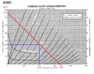
Let's take 6L6 wired in triode, with a 200V B+ and a 10k p-p primary impedance. I want to run the tube at 200V plate-to-cathode and 50mA plate current (10W plate dissipation). All nice even numbers to work with.
1/4 of 10k is 2.5k, so do I...
1) Find the point where B+ of 200V and Ip of 50mA intersect (at about -12V grid bias), and then...
2) Derive a 2500 ohm loadline from that?
That would look like the loadline in the attached graphic:
--
Attachments
- Home
- Amplifiers
- Tubes / Valves
- How To Draw Load Line With Output Transformer ?