My line voltage is 124 VAC at the moment. A little on the high side, My Phase Linears with E+I trannies and the Yamaha P2200 with a Toroid are dead quiet. I am tempted to put my scope with a 10 to 1 probe, on the line, don't know if there is any point to that.
If you have a filament transformer make a step down autotransfomer, that might clean up the noise.
I am tempted to put my scope with a 10 to 1 probe, on the line, don't know if there is any point to that.
It could be potentially lethal !
Never ever try connecting a (grounded) scope lead across direct mains voltage.
I bought the amp (Crest CA-18) used a few months ago, and it has had a noisy transformer from the start. I have used a wooden dowel as a stethoscope (we used this procedure to find noisy bearings in IMAX projectors. The hum/buzz seems to come from the windings and not the nylon core that is glued into the centre of the trans. I mention this because I don't think isolating the trans from the cabinet would help. The toroid is not vibrating the cabinet, I believe the noise source is direct from the windings.
Hi,
You can use the scope to read the AC but you must use the scope inputs in deferential mode. That will float the inputs. You need to use two probes. If you do not know how to do it Please, follow Mooly advice.
You can use the scope to read the AC but you must use the scope inputs in deferential mode. That will float the inputs. You need to use two probes. If you do not know how to do it Please, follow Mooly advice.
The only way to safely test AC mains is with all of your test gear floating. Hand held multimeters are nice because they run off a battery. If you need to use a scope a battery powered one would be best. If all you have is a mains powered one you may have to resort to a car battery and inverter. Just floating the inputs may not be enough as the common mode voltage to ground may be excessive. Even operating off a battery I'd attenuate AHEAD of the probes to get the common mode and differential voltages down first.
Not unless it is designed to be floated. The number of times I have come across oscilloscopes with the earth lead disconnected.The only way to safely test AC mains is with all of your test gear floating
If you want to check your mains waveform, just connect a 12V transformer across the mains and monitor the secondary
I'm told by many here that a Toroid passes HF better than an EI.
On that basis, using a toroid as the step down isolator should let one see more of the HF.
But I would not expect much VHF to register.
A test that would be worth doing is to use a mains "wireless" coms device and watch the scope pic change as the coms is turned on and off !
On that basis, using a toroid as the step down isolator should let one see more of the HF.
But I would not expect much VHF to register.
A test that would be worth doing is to use a mains "wireless" coms device and watch the scope pic change as the coms is turned on and off !
Not unless it is designed to be floated. The number of times I have come across oscilloscopes with the earth lead disconnected.
If you want to check your mains waveform, just connect a 12V transformer across the mains and monitor the secondary
Completely isolated power supply. Transformers and SMPSs can both transmit HF garbage right through them. In addition to the "chopping off the ground pin" hazard. Battery power eliminates the hazards and the potential for signal contamination.
A 12V transformer does you no good looking for DC on the mains.
The hum/buzz seems to come from the windings and not the nylon core that is glued into the centre of the trans. I mention this because I don't think isolating the trans from the cabinet would help. The toroid is not vibrating the cabinet, I believe the noise source is direct from the windings.
Peter.
I didn't read the whole thread,But let me tell you why and where you are getting this noise from.
It comes from core saturation, reason is that this tranny was made by someone who don`t know what audio power transformer needs to be.
You can`t fix it in any other way then drilling out the center potting, and then undoing the seconderies away, and adding some 2~3% more copper wire to primary winding and then wind back the secondarys with same percentage added....
It`s not such a big deal.. but it can take you several houres if you have the time for it.....
If not, then you can always order a new transformer made to your spec.
Last edited:
Hi Ben
There are 16 wires coming from this transformer, I think rewindig is beyond me. Am I wrong in thinking that core saturation would happen when the transformer is under ( heavy) load? The amp weighs 77 pounds and is mostly transformer. It has a max Primary input current of 36 amps at 120 VAC
As mentioned before, the noise is worse when a microwave oven is in use, and my "DC blocker" was not effective.
Core saturation is worse under light load. Increase the load and the effective flux will decrease because of leakage reactance. But magnetostriction between windings increases with load current, and if that is the source of the noise it will get worse at high load. It really depends on what is dominant.
Another possibility is a loose, corroded (or even open) neutral back at your breaker box on the service entrance side. Do you have lights in your house that get dim and bright? If this condition exists a high load on one leg of your mains will cause that side to drop and the other to rise. A microwave is typically the highest load of any one appliance that runs off only one side of your mains. If it's on the opposite leg to the amp, when the micro is on the amp sees a high line. You will get this to some degree even if the neutral connection is good, but it should be only a volt or two if that. If it's more there is a problem. Ranges, AC, dryers run off both legs and are not affected. The amplifier itself could draw a lot of current, but if it's playing quietly enough to hear the buzz it's not drawing much.
Another possibility is a loose, corroded (or even open) neutral back at your breaker box on the service entrance side. Do you have lights in your house that get dim and bright? If this condition exists a high load on one leg of your mains will cause that side to drop and the other to rise. A microwave is typically the highest load of any one appliance that runs off only one side of your mains. If it's on the opposite leg to the amp, when the micro is on the amp sees a high line. You will get this to some degree even if the neutral connection is good, but it should be only a volt or two if that. If it's more there is a problem. Ranges, AC, dryers run off both legs and are not affected. The amplifier itself could draw a lot of current, but if it's playing quietly enough to hear the buzz it's not drawing much.
An externally hosted image should be here but it was not working when we last tested it.
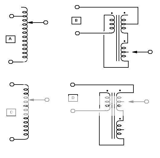
Making a filament transformer stand in for a Variac.
Type C is cut only, type A can also boost.
For 120V use a 6.3VCT x 2, Use a 12.6VCT for 240V.
I was able to find a 6.3VCT x2 for only $15, gives five 3.15V steps.
(general idea, use whatever you can find/need)
Last edited:
I understand using an extra winding, or two, to change the primary turns,
But I can't follow your diagrams C & D.
One core equals one transformer. Where is the 6Vac CT transformer?
Could you explain what C and D are showing?
But I can't follow your diagrams C & D.
One core equals one transformer. Where is the 6Vac CT transformer?
Could you explain what C and D are showing?
You have the primary and secondary wound in series across the mains.
You can then tap off across the original primary winding, the first CT on secondary 1, the end the first secondary, the CT of the second secondary and finally at the top of the second secondary in which case no reduction in the mains voltage.
It should be noted that these schemes provide NO MAINS ISOLATION - SO BE CAREFULL.
You need to feed the output of the into another transformer wired as you would normally.
Neat trick djk - thank you for sharing!
😎
Hi Ben
There are 16 wires coming from this transformer, I think rewindig is beyond me. Am I wrong in thinking that core saturation would happen when the transformer is under ( heavy) load? The amp weighs 77 pounds and is mostly transformer. It has a max Primary input current of 36 amps at 120 VAC
As mentioned before, the noise is worse when a microwave oven is in use, and my "DC blocker" was not effective.
Well, I'd say if its better with your DC blocker in situ and the microwave OFF, then its likely this is the major cause of your problem.
I would not try to rewind and re-install a transformer with 36 leads - you are asking for trouble unless you are confident and very well organized.
You are describing an autotransformer using a 240:6+6Vac isolating transformer.You have the primary and secondary wound in series across the mains.
You can then tap off across the original primary winding, the first CT on secondary 1, the end the first secondary, the CT of the second secondary and finally at the top of the second secondary in which case no reduction in the mains voltage.
It should be noted that these schemes provide NO MAINS ISOLATION - SO BE CAREFULL.
You need to feed the output of the into another transformer wired as you would normally.
Neat trick djk - thank you for sharing!
😎
Is that what DJK drew in diagrams C & D.
He needs to change his description so that becomes clear.
Autotransformer VA rating
When using a standard isolating transformer wired to become an autotransformer, one finds that the output VA is MUCH higher than the VA rating of the donor transformer.
Take the 240:6+6Vac 120VA transformer.
Wire up the two six volt windings in series and in phase with the 240volt primary. ( I deliberately chose 240Vac & 120VA because it makes the arithmetic simpler).
The total windings voltage is 240+6+6= 252Vac The extra voltage rating is 12/240 = 1/20th
The VA rating when the top tapping is used (i.e. Live In connected to Live out) is limited by the fuse or MCB fitted in the supply.
When any of the lower taps are used the maximum output current is limited by the CURRENT rating of the secondary. The secondary current rating is 120VA/(6+6) = 10Aac
The autotransformer has a VA rating of 240Vac*10Aac = 2400VA
i.e. 20times the donor transformer.
1/20th that's the ratio we get for VA rating increase.
If the transformer were a 115:15+15 Vac 100VA, then the autotransformer rating becomes 100VA*115/(15+15) = 383VA
Last edited:
C is a standard Variac autoformer, D is the transformer equavalent (wired as an autoformer).
If someone can't figure that out then they should not be fooling around with line voltage.
If someone can't figure that out then they should not be fooling around with line voltage.
I thought your diagrams A & C were a representation of a Variac.C is a standard Variac autoformer, D is the transformer equavalent (wired as an autoformer).
A being step up as well as step down. C being step down only.
I can't figure B & D out because there is a reference to a 6V CT as if it meant a transformer.Making a filament transformer stand in for a Variac.
But it may be you meant that we should add a pair of 3Vac windings.
You could at least make that clear !
Last edited:
Hi Folks;
I thought I should chime in since I started this mess. I actually do have a variac but small. I assume all the talk of filament transformers etc is to reduce the line voltage. Can I very slowly turn up the variac, powering the Crest? The Crest has a soft start, which may be a problem when it kicks into full, but if it works, you are leading me to believe that the buzz at 'saturation', so the buzz will reduced 'dramatically' below a certain line voltage (?).
My variac rig is fused, so it might be worth a fuse or two, to experiment.
This may be important;
My house has it's own hydro transformer on a pole outside (rural)
The Toroid buzz was particularly bad this morning, the microwave still made it worse.
I replaced the microwave with a toaster (resistive load); no addition buzz with toaster.
I moved Microwave to opposite phase, same increase in noise...I think this is significant because; and please correct me if I am wrong: The hydro transformer has a 240 VAC centre tapped secondary. A change in load (or introduction of noise) in one half of the secondary may be reflected to some degree, in the other half of the secondary (other phase), BUT.. how could a DC shift in one phase be transferred into a DC shift in the other phase.
What I am getting at is; Is it possible that the Toroid is reacting to noise rather than DC?
- Status
- Not open for further replies.
- Home
- Amplifiers
- Solid State
- Toroidal Transformer Noise