is there an attachment that I can't see?Here is how the DC blocker using only diodes works.
Note that with a high value capacitor will short out the diodes at AC do they will dissipate very little power. Without the cap, toy will need some subbering and on a big amp, some heatsinking.
OK, I see the pdf attachment now.
That analysis only applies when the DC is added to a symmetrical wave form.
Where the waveform has no DC added and the waveform is asymmetrical, then the +ve half waves do not cancel the -ve half waves and the core becomes saturated in the direction that has the higher average current.
The upper and lower half waveforms are constantly changing as different users apply different loads.
That is why we hear the growl change from second to second and often disappear completely when the upper and lower averages near enough cancel and not lead to core saturation.
Last edited:
Unfortunately, if you run the core - any type of core - into saturation, you will get harmonics and they will run hot
I have a very very very dirty main. I needed two DCB with AV Yamaha and AV Marantz.
Three weeks ago, one friday, the sound was horrrible in my AV Marantz and the EI transformers were very hot again.. I needed to connect ALL: DCB (proto) + DCB + DCBx2 !!!
Arter it, I need only two DCB to DC but with three and four DCB the sound was better. Why? The riple!!!
Three weeks ago, one friday, the sound was horrrible in my AV Marantz and the EI transformers were very hot again.. I needed to connect ALL: DCB (proto) + DCB + DCBx2 !!!
Arter it, I need only two DCB to DC but with three and four DCB the sound was better. Why? The riple!!!
Last edited:
is there an attachment that I can't see?
OK, I see the pdf attachment now.
That analysis only applies when the DC is added to a symmetrical wave form.
Where the waveform has no DC added and the waveform is asymmetrical, then the +ve half waves do not cancel the -ve half waves and the core becomes saturated in the direction that has the higher average current.
The upper and lower half waveforms are constantly changing as different users apply different loads.
That is why we hear the growl change from second to second and often disappear completely when the upper and lower averages near enough cancel and not lead to core saturation.
You are right - the DC will be moving around dependent upon the loads being switched in and out. But, the idea of the blocker is to ensure anything below +-2Vbe (assuming a bridge) is not applied to the core - once the AC voltage exceeds the +-2Vbe, its dV/dt - no DC.
Note my model is crude - it was just to show the concept and is not a fully worked example
I have a very very very dirty main. I needed two DCB with AV Yamaha and AV Marantz.
Three weeks ago, one friday, the sound was horrrible in my AV Marantz and the EI transformers were very hot again.. I needed to connect ALL: DCB (proto) + DCB + DCBx2 !!!
Arter it, I need only two DCB to DC but with three and four DCB the sound was better. Why? The riple!!!
If I understand you correctly, you say you had to connect two DCB in series to stop the growling and the sound only got better when you put 3 or 4 in series.
Indeed, if your mains had a lot of DC on it you could end up with that. Rod Elliot says that in most cases its only a few hundred mV - looks like in your situation though it is much worse.
Have you identified what equipment is causing it? In EU there are regulations against this type of equipment.
The problem is generated outside my home.
By the way, I have connected my PC (with my cheap -€43- Bequiet! L8 400W, with 15mV/200Watts ripple at 5V). The sound from my USB DAC (ODAC) is much better!. Well I use Schaffner RFI/EMI filters and RFI Würth ferrites 150Khz too.
-> bequiet! Pure Power L8 400W Review | KitGuru - Part 6
The answer, my friend, is blowing in the riple 🙂
Aleksandar (al_tsankov) is building a DCB x4 to me. With the big EPCOS off course.
Last night he send me some pictures:
Enhanced images by me.
Four PCBs assembled:
Box without black paint and without aluminum panel front:
The aluminum front, anodized/brushed and laser engraved with:
ATL Hi-Fi
DC & Riple Blocker x4 ME
ME = Maty edition
Why? Because I love the big EPCOS and his great ability to reduce riple.
ATL Hi-Fi
DC & Riple Blocker x4 ME
ME = Maty edition
Why? Because I love the big EPCOS and his great ability to reduce riple.
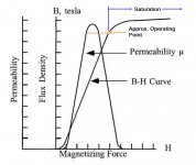
My experiences of toroidal transformer noise is that most transformer manufacturers are designing them with the operating point to close to the core saturation region, to save copper and weight. Ordinary toroids are calculated with a magnetizing force up to 1.7 to 1.8 Tesla with an oriented type M6 core.
The only cure for this saturation noise is to lower the mains voltage a few percent and the noise is usally gone.
This also explains the noise fluctuations as the mains fluctuate! Check with a volt-meter to confirm.
Back in the 1960's when there were common with black & white TV sets with transformerless half-wave rectifiers, the toroidal cores in many amps started to buzz when the TV was set on even in another room. It took some time to figure out what happened at that time when mains toroidals were new.
It was the TV that caused DC shift on the mains by its half-wave rectifier.
(TV's were made like that, to be used by 220VAC or 220VDC mains, that were common in many places)
The cure at that time was to insert one electrolytic capacitor of around 5-10000uF/10 to 16Volt in series with the mains and one diode parallel to the cap, to block reverse voltage exceeding 0.7V over the cap.
If the buzz was still there (the diode conducted), you just flipped the mains contact in the outlet to get the DC rightly polarized over the cap. If there were more TV sets on the same mains, you had to flip there plugs, so they were sending DC at the same polarity.
All this in at that time 220VAC mains country.
Matys problem is probably not DC at the mains but core saturation.
If you have a variac (variable transformer) it is easy to pin the problem.
Otherwise you can f.ex use a smaller transformer (1/10 of power of the device transformer) with a 12VAC secondary and connect the primary to the mains and the secondary out of phase in series with the mains transformer primary, to lower the mains voltage by 12VAC
Then you'll move the operating point to max permeability and out of the saturation knee, were the permeability (& inductance) goes down very quick and cause noise and heating losses.
See diagram below borrowed from Wiki: https://en.wikibooks.org/wiki/Electronics/Transformer_Design
Of course you lose some max output power, but the difference is almost inaudible.
Johan
Attachments
At the risk of being burned at the stake by a person not mentioned, the Crown circuit works.
Another thing also works (that has not been mentioned thus far), and that's using a Triac as a power switch (again, at the risk of being burned at the stake by a person not mentioned).
Another thing also works (that has not been mentioned thus far), and that's using a Triac as a power switch (again, at the risk of being burned at the stake by a person not mentioned).
My experiences of toroidal transformer noise is that most transformer manufacturers are designing them with the operating point to close to the core saturation region, to save copper and weight. Ordinary toroids are calculated with a magnetizing force up to 1.7 to 1.8 Tesla with an oriented type M6 core.
The only cure for this saturation noise is to lower the mains voltage a few percent and the noise is usally gone.
This also explains the noise fluctuations as the mains fluctuate! Check with a volt-meter to confirm.
Back in the 1960's when there were common with black & white TV sets with transformerless half-wave rectifiers, the toroidal cores in many amps started to buzz when the TV was set on even in another room. It took some time to figure out what happened at that time when mains toroidals were new.
It was the TV that caused DC shift on the mains by its half-wave rectifier.
(TV's were made like that, to be used by 220VAC or 220VDC mains, that were common in many places)
The cure at that time was to insert one electrolytic capacitor of around 5-10000uF/10 to 16Volt in series with the mains and one diode parallel to the cap, to block reverse voltage exceeding 0.7V over the cap.
If the buzz was still there (the diode conducted), you just flipped the mains contact in the outlet to get the DC rightly polarized over the cap. If there were more TV sets on the same mains, you had to flip there plugs, so they were sending DC at the same polarity.
All this in at that time 220VAC mains country.
Matys problem is probably not DC at the mains but core saturation.
If you have a variac (variable transformer) it is easy to pin the problem.
Otherwise you can f.ex use a smaller transformer (1/10 of power of the device transformer) with a 12VAC secondary and connect the primary to the mains and the secondary out of phase in series with the mains transformer primary, to lower the mains voltage by 12VAC
Then you'll move the operating point to max permeability and out of the saturation knee, were the permeability (& inductance) goes down very quick and cause noise and heating losses.
See diagram below borrowed from Wiki: https://en.wikibooks.org/wiki/Electronics/Transformer_Design
Of course you lose some max output power, but the difference is almost inaudible.
Johan
Very good points.
This Friday I had 235V. AV Marantz SR4500 without any DCB sounds good < 237V. I think that the EI transformer was designed to work at 220V +/- 8% and not 230V, like more cheap chinese audio electronics in these days.
Yes, I studied the variac solution and I have designed a "Maty edition" too.
Next day, morning Saturday, with DCBx2 I had good sound again and the EI transformer was "cold" but the sound was worse when I had DCB (proto) + DCB + DCBx2 in series.
And I connected again the four DCB until Tuesday. Then I take the decision to order a DCBx4 to AV Marantz (DCB (proto) + DCB + DCBx2 => AV Yamaha).
I have more DC and RFI/EMI in mains and RFI atmospheric too! 🙁
No.............. But, the idea of the blocker is to ensure anything below +-2Vbe (assuming a bridge) is not applied to the core ............
It is unbalance created by the unsymetrical waveform that creates the excess core flux. If that core flux temporarily exceeds the maximum flux for the core material, then during a part of that half waveform the normal primary current is exceeded, (due to a fall in inductive reactance) and you hear the growl.
Did DC blocker solve the overheating?
Or were they wound with too few primary turns for the supply voltage you gave them?
That makes two Members agreeing that DC is maybe not the problem. The problem may be saturation because the transformer is NOT DESIGNed to suit the full range of voltage available to Maty...........................
The only cure for this saturation noise is to lower the mains voltage a few percent and the noise is usally gone.
This also explains the noise fluctuations as the mains fluctuate! Check with a volt-meter to confirm...................
Mains powered electrical equipment sold in the EU must be designed to suit the full range of mains voltage allowed by the "harmonised" voltage that we have here.
That is 216Vac to 253Vac.
All retailers and importers MUST abide by that requirement.
I suspect that some transformer assemblers don't even know what "harmonised" means.
These assemblers should be put in jail!!!!!
Last edited:
No.
It is unbalance created by the unsymetrical waveform that creates the excess core flux. If that core flux temporarily exceeds the maximum flux for the core material, then during a part of that half waveform the normal primary current is exceeded, (due to a fall in inductive reactance) and you hear the growl.
The unbalance is CAUSED by a DC component., The flux will not be imbalanced once the DC component is removed. Even if there is 2nd harmonic present as well, which will still make it *look* imbalanced. But if you integrate the waveforrm over one complete two pi period, you get zero.
adding some second harmonic does change the shape of the waveform.
But does not make the unbalance of current.
Chopping the top off one side of the waveform does change the unbalance.
Changing the chopped tops on both the upper and lower halves of the waveform will change the unbalance if the two "chops" are not identical.
Adding some interfence spikes that are different in the upper half from the lower half will change the unbalance.
It is not a true added DC component that is our potential saturation problem.
It's the unbalance of the current waveforms that create the saturation effects.
It can increase and then decrease. It can swap over from excess on the upper through zero to excess on lower.
This is probably why the growl is not continuous. It rises and falls. It is worse at some periods of the day and inaudible at other times.
But does not make the unbalance of current.
Chopping the top off one side of the waveform does change the unbalance.
Changing the chopped tops on both the upper and lower halves of the waveform will change the unbalance if the two "chops" are not identical.
Adding some interfence spikes that are different in the upper half from the lower half will change the unbalance.
It is not a true added DC component that is our potential saturation problem.
and when the upper and lower do not give "zero".if you integrate the waveforrm over one complete two pi period, you get zero
It's the unbalance of the current waveforms that create the saturation effects.
It can increase and then decrease. It can swap over from excess on the upper through zero to excess on lower.
This is probably why the growl is not continuous. It rises and falls. It is worse at some periods of the day and inaudible at other times.
Last edited:
I don't know why the DC blocking capacitor solution works. But I have used it and it does work.
My mains runs are typically 245Vac. That takes typical toroid transformers much closer to saturation than does 220Vac or 230Vac. I can understand why some of my toroids become occasional growlers. Because they run much closer to saturation and only need a bit more to become a problem.
So I implement the Capacitor version of the DC blocker.
@Andrew, the problem is the DC without doubt.
AV Yamaha RX-V2700 has the same problem: heat. This Friday the EI transformer was very hot too.
I suspect about Marantz's EI transformer (220V or 230V) but not about Yamaha's EI.
Trust me, I took a long time researching about my problems and I went by solving. So I have not changed amplifier to listen to music with computer or I do not have a more advanced DAC.
Feb 02, 2014
USB Isolator: iFi iUSB vs TeraDak U9VA + Teralink ADuM4160. Filtros Schaffner. Lampizator: AC filter DIY ESA SILK. Estabilizador / regulador de tensión / voltaje. Isolation / Balanced transformer. DC Blocker / Blocking. PC SILENCIOSO en Aussar. Vari
Remember, this Friday I measured 235V. With this voltage the two AV amplifiers sound good.
If someone has more DC, the best solution is my DC & Riple Blocker x2 (two in series), with EPCOS 18000 microF 105ºC to attenuate the ripple too.With two we sure the shot.

If someone has more DC, the best solution is my DC & Riple Blocker x2 (two in series), with EPCOS 18000 microF 105ºC to attenuate the ripple too.With two we sure the shot.

No.
It is unbalance created by the unsymetrical waveform that creates the excess core flux. If that core flux temporarily exceeds the maximum flux for the core material, then during a part of that half waveform the normal primary current is exceeded, (due to a fall in inductive reactance) and you hear the growl.
Hi Andrew,
Sorry to say you're wrong. It is the DC component created by unsymmetrical unbalanced wave forms, steady or pulsating that saturates the core.
You even admit a capacitor in series fix the problems in your cases.....
Anyway I don't know if many members here fully understand the difference between DC saturation and to high flux saturation of a noisy core.
Sometimes even a lose winded toroid core will make noise under normal conditions!
Maty, please measure and tell us here in this thread what the total DC voltage is over your serial connected capacitors in the filter you use.
You can use a normal meter set to DC.
It would show the residual filtered DC component you have in your mains.
Be carefull as there is mains voltages around when you measure!!
One hand in the pocket if you're in a grounded environment.....
A good rule in these days of mains carrying TV chassis...... 😱
Johan
- Status
- Not open for further replies.
- Home
- Amplifiers
- Solid State
- Toroidal Transformer Noise