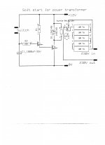
3 DC-amplifiers need soft start of the toroidal transformers. This makes sense, because of double psu's with two 500VA transformers, 4 x 35A bridges and 2 x 20.000uF/63V . Rail voltage +-56V.
We have never used softstart before .....delay start with DC detection/ speaker protection is already made.... , but not soft start.
The thought was that softstart could extend the life of the capacitors.
.....found a simple soft start circuit. Attached
The circuit needs a 12VDC supply, but is the 5 resistors of 10 R/7W sufficient for 1KVA transformer...hmm? If the delay is a couple of seconds the 50R - 35W might not be sufficient?
What does the experience say?
Rgds. gudmund
Attachments
Last edited:
That's about as simple a circuit as you will find.
I designed a soft start using a PIC micro with a triac.
The PIC ran from a dropper resistor into a smoothing capacitor off the mains.
I used an opto-coupler to drive the triac gate.
It worked fine but needed quite a big heat sink for the triac.
But it could cope with up to a 3000watt power amp.
I designed a soft start using a PIC micro with a triac.
The PIC ran from a dropper resistor into a smoothing capacitor off the mains.
I used an opto-coupler to drive the triac gate.
It worked fine but needed quite a big heat sink for the triac.
But it could cope with up to a 3000watt power amp.
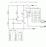
3 DC-amplifiers need soft start of the toroidal transformers. This makes sense, because of double psu's with two 500VA transformers, 4 x 35A bridges and 2 x 20.000uF/63V . Rail voltage +-56V.
We have never used softstart before .....delay start with DC detection/ speaker protection is already made.... , but not soft start.
The thought was that softstart could extend the life of the capacitors.
.....found a simple soft start circuit. Attached
The circuit needs a 12VDC supply, but is the 5 resistors of 10 R/7W sufficient for 1KVA transformer...hmm? If the delay is a couple of seconds the 50R - 35W might not be sufficient?
What does the experience say?
Rgds. Kim
Usually just a few ohms is sufficient.
That's about as simple a circuit as you will find.
I designed a soft start using a PIC micro with a triac.
The PIC ran from a dropper resistor into a smoothing capacitor off the mains.
I used an opto-coupler to drive the triac gate.
It worked fine but needed quite a big heat sink for the triac.
But it could cope with up to a 3000watt power amp.
This inrush current delay is much more complicated than I thought.
I'm not very fond of a triac in the circuit .... could you show me a softstart circuit proposal, which includes resistors and a suitable time delay ( how long is a suitable delay? 1 second, or two seconds? or even shorter time?) ..... and including a in line fuse.
I tried to read Rod Elliott ESP suggestions of how to make a "Soft-Start Circuit For Power Amps"....and I am confused . Rod says that the use of resistors in many cases is preferred .
Rod Elliott said:
"If the relay fails to operate because you didn't listen to me and used the amp's supply, the thermistor will (in theory) become a low resistance due to the current flow and the fuse will blow. However, if current is too high due to a major fault, the thermistor may explode before the fuse has a chance. I'm unsure why some people insist that the thermistor is somehow "better" than resistors - it isn't, and in some cases may even be a less robust solution. As noted below, a resistor (or thermistor) value of about 50 ohms (230V) or 25 ohms (120V) is a pretty good overall compromise, and works perfectly with transformers up to about 500VA. The resistance should be reduced for higher power transformers."
Link to Rod Elliott, ESP: Soft-Start Circuit For Power Amps
Gudmund
If you do a search on DIYAUDIO you will find numerous threads about cold start circuits.
I think the relay can be off for quite short times.
I think the relay can be off for quite short times.
The 50r of limiting resistor will limit the current to ~4.5Aac during the first couple of cycles of the mains.
This initial current will not blow a T2.5A fuse. I have tested this on 240Vac
It may even work with a T2A fuse, but I have not tested this.
Those fuse ratings suit transformers of 400VA to 600VA.
For 1000VA you need a fuse of T4A or T5A to operate on 230Vac.
This size of fuse will not blow if your resistance is ~30r
This is the soft start resistance you need for a 1000VA transformer operating on 220/240Vac.
But, you have two 500VA. These should be fused separately and use separate poles of the relay. Your relay shows two sets of poles.
500VA needs a fuse rating of T2A, or T2.5A
An amplifier running full tilt from a 500VA transformer will run forever on a T2A fuse.
This will work with a 50r or 60r resistor.
But you need two resistors and two relay poles for TWO transformers.
Is the switch a short to feed 12V to the delay capacitor?
You need a resistance to create an RC value, the delay.
For a 1second delay try 3k3. This gives a 3.3second RC.
The capacitor will charge to ~60% of 12V in 3.3second.
But, you only need ~1.4V to turn on the two transistors. The cap will charge quite quickly to 1.4V
I'd guess that 1.4V/7.2V will take 1/2 to 1second.
The 1k0 resistor feeding the first transistor will pass ~10mA to the base of the second transistor.
The second transistor should run in saturated mode with an Ic:Ib of ~ 10:1
That 1k0 resistor allows a relay current of ~100mA. That's a very low resistance 12V relay coil.
Measure your relay coil, find what current has to pass through the second transistor to fully turn the relay ON.
Then divide by that 10:1 ratio to find the first transistor Ic. Use this IC to determine the new value for the 1k0 resistor.
Is the switch a short to feed 12V to the delay capacitor?
You need a resistance to create an RC value, the delay.
For a 1second delay try 3k3. This gives a 3.3second RC.
The capacitor will charge to ~60% of 12V in 3.3second.
But, you only need ~1.4V to turn on the two transistors. The cap will charge quite quickly to 1.4V
I'd guess that 1.4V/7.2V will take 1/2 to 1second.
The 1k0 resistor feeding the first transistor will pass ~10mA to the base of the second transistor.
The second transistor should run in saturated mode with an Ic:Ib of ~ 10:1
That 1k0 resistor allows a relay current of ~100mA. That's a very low resistance 12V relay coil.
Measure your relay coil, find what current has to pass through the second transistor to fully turn the relay ON.
Then divide by that 10:1 ratio to find the first transistor Ic. Use this IC to determine the new value for the 1k0 resistor.
Thanks, this is most kind of you....I have to read this to understand.
Yes , the switch should activate the circuit, but you say that I need a resistor approx. 3K3 from the switch contact point before the capacitor , and that your delay guess would be approx 1/2 second. I have measured the Omron relay coil to 262 R. I think I have to make a test setup
rgds. Gudmund
262r gives a relay coil current of ~46mA.
Aiming for a 10:1 ratio means the base current needs to be around 4mA or 5mA.
This is the current that must pass that 1k0.
You have ~10.6V available for 4 to 5mA
that needs a 2k2 or 2k4 resistor instead of the 1k0.
If you leave in the 1k0, you end up with ~5:1 ratio of Ic:Ib. It still works, it is still saturated.
The thing to remember is that the second transistor must run saturated so that it's Vce is as close to zero volts as possible. This also has the advantage that the switching transistor runs cold. The first transistor has to supply the base current that saturates the second transistor. Note that using a Darlington (even with it's 50000 hFE) does not achieve this. The Darlington drops ~800mVce and that produces some heat and reduces the voltage across the relay. The saturated 2ndQ drops ~50mVce.
Look at the possibility of using a plastic film time delay capacitor (very low leakage = consistent timing). And a much larger timing resistor. I typically use 1uF, or 2u2F, MKT and 220k and the timer always works consistently.
I sometimes raise the trigger voltage by adding an LED between the first and second transistors. Instead of triggering @ ~1.4V, it triggers at ~3.1V and thus takes twice as long.
Last edited:
Here's an article worth reading.
I usually implement the current saving resistor and drive the 12V relay from 15V tro 18V
I make added R ~= to coil R.
What?s All This Solenoid Driver Stuff, Anyhow? | Analog content from Electronic Design
All Bob Pease "stuff" is worth reading.
The pdf is 2.4M, quite a bit above the Forum limit.
Does anyone know how to attach a "too big" pdf?
Last edited:
262r gives a relay coil current of ~46mA.
Aiming for a 10:1 ratio means the base current needs to be around 4mA or 5mA.
This is the current that must pass that 1k0.
You have ~10.6V available for 4 to 5mA
that needs a 2k2 or 2k4 resistor instead of the 1k0.
If you leave in the 1k0, you end up with ~5:1 ratio of Ic:Ib. It still works, it is still saturated.
The thing to remember is that the second transistor must run saturated so that it's Vce is as close to zero volts as possible. This also has the advantage that the switching transistor runs cold. The first transistor has to supply the base current that saturates the second transistor. Note that using a Darlington (even with it's 50000 hFE) does not achieve this. The Darlington drops ~800mVce and that produces some heat and reduces the voltage across the relay. The saturated 2ndQ drops ~50mVce.
Look at the possibility of using a plastic film time delay capacitor (very low leakage = consistent timing). And a much larger timing resistor. I typically use 1uF, or 2u2F, MKT and 220k and the timer always works consistently.
I sometimes raise the trigger voltage by adding an LED between the first and second transistors. Instead of triggering @ ~1.4V, it triggers at ~3.1V and thus takes twice as long.
Thank you for your help.
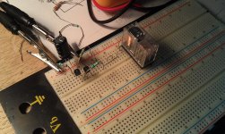
As amateur, I have tried to solve the problem. Suggested circuit change attached.
I have started a 500VA toroidal transformer up a couple of times with approx. 2,5-3.0 seconds delay without burning out the 50W resistor.
I don't know how many cycles have to pass before the large resistor is switched off?
I think the circuit works ok.....?
I know that you are right when you say that a plastic film time delay capacitor is better..more accurate...but the circuit was here with the two BC547...it's cheap and it works.
Regards Gudmund.
Attachments
I don't like R3.
It is very usefull for trimming the time delay.
But it acts in a similar manner to electrolytic leakage.
Look at the 9second values.
Vr3 = 12V * ( 22k/(22k+68k)} if capacitor charging current plus capacitor leakage plus base current are zero milli-amps.
You have a maximum capacitor charging voltage of 2.93V.
You need to get to ~50% of that to trigger the relay.
If base current and electrolytic leakage have finite values you can reach a point where you never achieve trigger voltage.
The relay does not pull in.
eg, try Ib=5mA/200 = 0.025mA and Ileak = 0.05mA.
At a rough calculation Vr3 becomes <=1.2V. The relay may not trigger.
If the electrolytic is freshly reformed then it triggers
If the elctrolytic has not be freshly reformed, then leakage could be very much higher.
I much prefer to do without R3 and adjust timings using the basic RC or by increasing the trigger voltage to above the existing 1.4V, but well below the 12V charging voltage.
You can with appropriate component values get very reliable triggering of the relay using circuits like this.
I have done a few.
I prefer using a 555 timer. It costs much the same and is very consistent.
Last edited:
I don't like R3.
It is very usefull for trimming the time delay.
But it acts in a similar manner to electrolytic leakage.
Look at the 9second values.
Vr3 = 12V * ( 22k/(22k+68k)} if capacitor charging current plus capacitor leakage plus base current are zero milli-amps.
You have a maximum capacitor charging voltage of 2.93V.
You need to get to ~50% of that to trigger the relay.
If base current and electrolytic leakage have finite values you can reach a point where you never achieve trigger voltage.
The relay does not pull in.
eg, try Ib=5mA/200 = 0.025mA and Ileak = 0.05mA.
At a rough calculation Vr3 becomes <=1.2V. The relay may not trigger.
If the electrolytic is freshly reformed then it triggers
If the elctrolytic has not be freshly reformed, then leakage could be very much higher.
I much prefer to do without R3 and adjust timings using the basic RC or by increasing the trigger voltage to above the existing 1.4V, but well below the 12V charging voltage.
You can with appropriate component values get very reliable triggering of the relay using circuits like this.
I have done a few.
I prefer using a 555 timer. It costs much the same and is very consistent.
Could you show me what you mean with the "basic RC"? Do you have drawings of the triggering relay circuits you have done?
A small microcontroller is an easy solution. An Arduino nano is very cheap and is simple to integrate into the circuit to turn on an inrush relay through a resistor, then a main power relay a couple seconds later. Timing adjustments become a quick adjustment of a sketch, then upload the software, no hardware changes required.
basic RC = R2 plus C1
Attachments
Last edited:
Another option is to replace the rectifier bridge of the amplifier with a compound SCR-diodes bridge: you can implement the soft start either by phase control, or by adding diodes with series resistors in parallel with the SCR's.I'm not very fond of a triac in the circuit ....
That way, you won't incur additional losses of the triac, since the conduction loss of a diode is comparable to that of an SCR.
This scheme only takes care of a capacitive inrush obviously, not that caused by a possible saturation of the core
basic RC = R2 plus C1
Ok..understand now what you mean by basic RC.
I can't get your asc. files right on the pc. Do you have the drawings in PDF?
Sorry, no.
I'm pretty poor with modern PCs and I find it easier to just draw with pencil and paper.
I'm pretty poor with modern PCs and I find it easier to just draw with pencil and paper.
Ok..understand now what you mean by basic RC.
I can't get your asc. files right on the pc. Do you have the drawings in PDF?
Here's pdf files.
Attachments
- Status
- Not open for further replies.
- Home
- Amplifiers
- Solid State
- Simple soft start current limiter for DC-amp