and when the initial charging current subsides the dissipation reduces (heat = I²R) and the resistance goes back towards the cold value.
The running current of these SMPS is FAR LOWER than the initial surge current that charges the mains connected capacitor/s.
The running current of these SMPS is FAR LOWER than the initial surge current that charges the mains connected capacitor/s.
Which part does not fit with your experience?
when the initial charging current subsides
dissipation reduces (heat = I²R)
the resistance goes back towards the cold value
running current of these SMPS is FAR LOWER
the initial surge current that charges the mains connected capacitor/s
Which part does not fit with your experience?
you are the guru, you figure it out.....
Hi all,
I am trying make a softstart for trafo(800VA with 60kuF downstream) using the TI app note http://www.ti.com/lit/an/snaa057b/snaa057b.pdf .
However, I am unsure of the clearances to be maintained for the mains application. I have currently kept the clearances as min 56mils between line and neutral and tried to separate the signals from mains as far as possible. Can someone take a look and comments?
reg
prasi
some designators are as follows
1. V+ is the signal of V+ from PSU and GND is the PSU ground.
2. PRI-N is the trafo primary wire where "neutral" is connected.
3. PRI-L is the trafo primary wire where "line" is connected.
4. SW1 and SW2 are the switch points for the "line".
reg
prasi
Also I want to be able to use this from +/-50VDC to +/-70VDC😀
Attachments
Last edited:
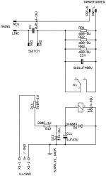
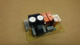
For a past few yeares I am using a bellow simple soft-start. Works really fine.
The power to the trafo can be switchen ON/OFF with a small current switch (approx 16-18mA). There is DC blocker and a bit of the mains filtration on the board.
The relays are powered by the reactance PSU (220nF capacitor). It may be usefull for someone.
But IMHO paralleling NTC with the triac is the modern way to go for.
Regards
Attachments
A very common problem with amp faults is soft start relay going bad.
I use a triac in my soft start design.
I use a small microcontroller to ramp up the phase angle until it gets to full power.
Only problem is triac needs quite a big heat sink for larger powered amps.
I use a triac in my soft start design.
I use a small microcontroller to ramp up the phase angle until it gets to full power.
Only problem is triac needs quite a big heat sink for larger powered amps.
For a past few yeares I am using a bellow simple soft-start. Works really fine.
The power to the trafo can be switchen ON/OFF with a small current switch (approx 16-18mA). There is DC blocker and a bit of the mains filtration on the board.
The relays are powered by the reactance PSU (220nF capacitor). It may be usefull for someone.
But IMHO paralleling NTC with the triac is the modern way to go for.
Regards
Hi Borys,
Interesting implementation. Can you detail how the switch works? Also post layout? I would like understand the clearances used between mains and signal.
reg
prasi
prasi
It works in very simple way. By shorting the SW pins (with small switch) you turning ON a small PSU for the relays. The PSU is made of 220nF capacitor, the reactance of that capacitor works like a constant current source, than voltage is rectified by the 4 diodes bridge and goes to the two relays connected in series. One of relays have 22uF capacitor and is switching the power ON to the transformer (threw the resistor network, reducing inrush current). After the big capacitor at the second relay is charged up the relay is shorting the inrush resistors and trafo gets what it wants.
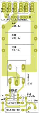
I kept the clearances of 6-8mm in between the mains tracks on pcb.
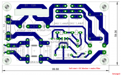
I am going to prepare a new layout anyway.
Now it is very important to use 24V relays with 1.44kR coils. If differend relays are used the 220nF cap needs to be recalculated.
Regards.
It works in very simple way. By shorting the SW pins (with small switch) you turning ON a small PSU for the relays. The PSU is made of 220nF capacitor, the reactance of that capacitor works like a constant current source, than voltage is rectified by the 4 diodes bridge and goes to the two relays connected in series. One of relays have 22uF capacitor and is switching the power ON to the transformer (threw the resistor network, reducing inrush current). After the big capacitor at the second relay is charged up the relay is shorting the inrush resistors and trafo gets what it wants.
I kept the clearances of 6-8mm in between the mains tracks on pcb.
I am going to prepare a new layout anyway.
Now it is very important to use 24V relays with 1.44kR coils. If differend relays are used the 220nF cap needs to be recalculated.
Regards.
Attachments
Thanks a lot Borys!. I will do a part search as per your schematic to see if I can locate the required parts.prasi
It works in very simple way. By shorting the SW pins (with small switch) you turning ON a small PSU for the relays. The PSU is made of 220nF capacitor, the reactance of that capacitor works like a constant current source, than voltage is rectified by the 4 diodes bridge and goes to the two relays connected in series. One of relays have 22uF capacitor and is switching the power ON to the transformer (threw the resistor network, reducing inrush current). After the big capacitor at the second relay is charged up the relay is shorting the inrush resistors and trafo gets what it wants.
I kept the clearances of 6-8mm in between the mains tracks on pcb.
I am going to prepare a new layout anyway.
Now it is very important to use 24V relays with 1.44kR coils. If differend relays are used the 220nF cap needs to be recalculated.
Regards.
Regarding my ckt posted (based on TI app note), Can some one guide me in selecting resistor values R11 and R12 and zener power rating for different supply voltages (from 50 to 70 VDC). I guess it will also depend upon the relay coil dissipation. I am thinking to use TE connectivity T90 relay that has 0.9W coil Power and res of 2560 ohms (36V pick up voltage).
reg
Prasi
Last edited:
- Status
- Not open for further replies.
- Home
- Amplifiers
- Solid State
- Simple soft start current limiter for DC-amp