I made a comparison between the two options and a "gold standard", plus a few other.
a) and b) are the gold standards, with and without bypassing.
That's the actual CCS impedance, measured with proper spice techniques.
c) and d) are the configurations tested by Gasboss: it is immediately apparent that d) stands out in a suspect way.
e) is the properly bypassed version
The second pic zooms on the remainder of the traces: they are all very close, and quite stable up to ~10KHz.
The standards are a bit lower, meaning the measured value are slightly optimistic, but not to problematic extent.
With a higher performance transistor, discrepancies could become larger.
Attachments


Last edited:
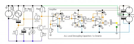
Perhaps we should be looking at something like this again:
I would power the amplifier with the separate +/- 12 V supply and increase the gain to allow for better resolution in the measured results.
I would power the amplifier with the separate +/- 12 V supply and increase the gain to allow for better resolution in the measured results.
I have reassembled the measurement setup with a jfet cascode in the collector leg.
Incredibly the same thing is happening with the 1 bjt + led CCS!
The figures are a bit more realistic 4~10M. But again with increasing impedance with increased signal frequency!
I've rechecked the amplifier. Its more or less flat from 50hz to 10Khz +/-0.2dB.
I've tried a different transistor in the CCS, same thing!
I'm sure I must be making a glaringly obvious mistake, but I can't see it.
Have attached a schematic of the new setup.
Attachments
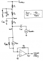
It seems to me that the virtual earth measurement technique in post #317, is quite reasonable for current source values less than 10mA such as are being discussed here. As long as the DC current is below the opamp's maximum output current, it looks solid.
I've drawn the current source below as its Norton Equivalent: a dc current in parallel with an undesired Norton equivalent resistance. When you carry out the standard small-signal analysis you find that Vout = Vin * (-1) * (RF/RBAD). Simple.
The rigmarole on top with R1, R2, Cbig, and TL431 provides added "line rejection" to remove unwanted AC signals ("noise") from Vsupply. TL431 does this at very low frequencies, and Cbig does it at high frequencies. Quiet supply node Vgood is at least 30dB quieter than Vsupply.
_
Attachments
Iam still perplexed by the behavior of the 1bjt&led current source. I tried a different led-a blue one with a higher Vf- and the same behavior. I also changed the decoupling cap across the led. In all cases impedance increased with increasing signal frequency!
I hooked up a 1mA 2 transistor CCS with this setup ( jfet cascode ) the behavior was as would be expected, though Z at 50 Hz was around 16M, quite a bit lower than with the other arrangement, although I didn't use identical transistors, also Rbias was 120k, possibly too high?
I discovered an amazing thing my 'scope can do. It can take the average of up to 128 samples, can recover a very clean signal from one swamped by noise! A very useful feature. 😀 😀 😀
It seems to me that the virtual earth measurement technique in post #317, is quite reasonable for current source values less than 10mA such as are being discussed here. As long as the DC current is below the opamp's maximum output current, it looks solid.
I've drawn the current source below as its Norton Equivalent: a dc current in parallel with an undesired Norton equivalent resistance. When you carry out the standard small-signal analysis you find that Vout = Vin * (-1) * (RF/RBAD). Simple.
The rigmarole on top with R1, R2, Cbig, and TL431 provides added "line rejection" to remove unwanted AC signals ("noise") from Vsupply. TL431 does this at very low frequencies, and Cbig does it at high frequencies. Quiet supply node Vgood is at least 30dB quieter than Vsupply.
_
I had read somewhere that the TL431 was quite a noisey regulator. Still I'll try it and see if it helps, I have some tl431 already.
As for the method of feeding into the virtual earth, I tried it and it was quite noisey, perhaps it would work better with a quieter CCS supply.
How does the output of the detector amp looks like at the oscilloscope?
Does it look like white noise or discrete frequencies (50Hz)?
How does it look with the current source disconnected?
Maybe the problem is the LED of the CCS. These devices are photodetectors too
and a very bad choice for a precision current source.
Does it look like white noise or discrete frequencies (50Hz)?
How does it look with the current source disconnected?
Maybe the problem is the LED of the CCS. These devices are photodetectors too
and a very bad choice for a precision current source.
How does the output of the detector amp looks like at the oscilloscope?
Does it look like white noise or discrete frequencies (50Hz)?
How does it look with the current source disconnected?
Maybe the problem is the LED of the CCS. These devices are photodetectors too
and a very bad choice for a precision current source.
The amp output is white noise, without a signal and slightly less white noise without the CCS connected.
I tried a different led and have tried a different transistor and coupling capacitor, yet similar behaviour, that is; increasing Z with increasing Freq.
I didn't expect the bjt_&_led CCS to be good, just wanted to make a comparison.
I made a test, with the transformer setup: mine has no magic: the impedance is a stable 6.6MΩ at low frequencies, slowly decreasing to 2.3MΩ at 10KHz.I tried a different led and have tried a different transistor and coupling capacitor, yet similar behaviour, that is; increasing Z with increasing Freq..
How boring....🙁
I made a test, with the transformer setup: mine has no magic: the impedance is a stable 6.6MΩ at low frequencies, slowly decreasing to 2.3MΩ at 10KHz.
How boring....🙁
Should I be questioning my sanity? 😀
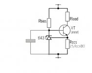
I came up with an idea for a CCS, see attached. I wasn't sure about the best value for Rbias, or for the need for the bypass capacitor, though I'm sure it's a neccesity for tl431 stability, not sure about the best value though?
Attachments
An interesting observation using my recently discovered oscilloscope feature.
In the attached image cleaned up using the signal averaging function, you can clearly see marked distortion, in the form of soft clipping of the negative peak of the sinewave from the output of the amplifier, this is not a problem with the amplifier, I've checked. This occurred at 5khz upwards with an input of (2.82Vpk-pk) 1 v RMS. Reducing the test signal to 1volt peak to peak appears to have minimized the problem.
In the absence of the noise cleaning facility previously, I was unable to see the waveshape with clarity, due to the noise. Could this account for the strange behaviour yesterday?
EDIT: This was not the bjt-led current source but the two bjt current source, but I intend to try retesting the led one again in order to examine the output waveform.
Attachments

Last edited:
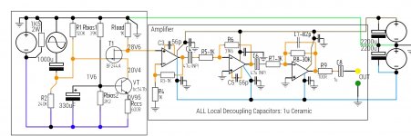
Some more results today with 2 transistor current source @ 1mA / 20VDC, using the jfet cascode setup.
Additionally I've charted the frequency response of the amplifier from 10Hz to 100Khz.
Measurements were taken with my 'scope using the averaging facility to clean up noise. These are the highest genuine looking results.
The CCS transistor was a bc547b
The feedback transistor was a bc169b ( an oldie )
The bias resistor ( the bc169's collector load ): 39K
Attachments
Last edited:
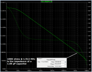
Hmm, 0.13 Gigohms at 100 Hz. I'm seeing 10X higher in LTSPICE simulation: 1.5 Gigohms at 100 Hz for a JFET cascode using the Richard Jaeger (post 260) connection. Admittedly I installed an arbitrary 1pF of stray capacitance modeling at every node. Who knows whether that's too low or too high.
_
_
Attachments
Last edited:
Hmm, 0.13 Gigohms at 100 Hz. I'm seeing 10X higher in LTSPICE simulation: 1.5 Gigohms at 100 Hz for a JFET cascode using the Richard Jaeger (post 260) connection. Admittedly I installed an arbitrary 1pF of stray capacitance modeling at every node. Who knows whether that's too low or too high.
_
I used a slightly different circuit , see post #343
At this point, I am happy with the amplifier, although it needs to be made more permanent, currently it is on a breadboard.
I think the assembly of the actual CCS under test could be at issue, with stray coupling ( capacitive) being the most likely culprit. I was thinking about the idea of guarding, I've seen it being used to neutralise abberant capacitive phenomenon. Currently my setup is a bit of a rats nest, probably why I've been reluctant to post pictures!
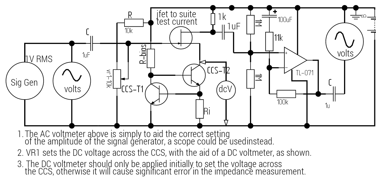
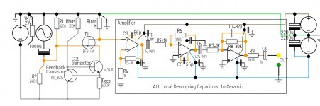
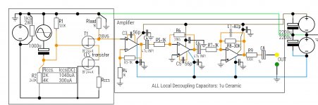
Just to clarify regarding the current measuring setup, see attached.
The bf244 jfet is part of the measurement setup, it serves the dual purpose of a modulating load and also to isolate the CCS itself from the measurement amplifier, which is connected at the drain of the jfet.
I chose the bf244 as it had the lowest capacitance of all the jfets I currently have.
Because the jfet has finite output impedance and capacitance the isolation won't be perfect. The bf244 is mounted physically close to the CCS transistor to minimize the effect of stray capacitive coupling to ground that would tend to pull down the actual measured impedance of the CCS itself.
If anyone would be willing to simulate my exact circuit, to see how the simulation compares with the actual result, I would be very greatful, as I don't have access to ltspice presently.
Also the 1000uF coupling capacitor between the signal gen and the jfet was replaced with a 1.5uF capacitor as the 1000u was taking forever to charge up. (RC = 80 seconds! )
Attachments
Last edited:
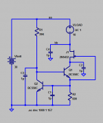
Had another go at measuring the 1 bjt current source, this time with just a potential divider and capacitor, instead of the led voltage reference. The same weird thing happened again, increasing impedance with increasing frequency. There was no signal distortion, I used my 'scope to do the measuring.
I can think of no other explanation! In any case this probably isn't such a good current source topology, I won't be making any more measurements on this type of CCS.
Attached is the schematic and a PDF of the measurement.
In the next post I will be posting the results of a simple 2 terminal CCS ( jfet and resistor )
Attachments
Next up a jfet + source resistor.
BF244A + 2K (1ma04)
BF244A + 4K (300uA)
Schematic and two sets of PDF results attached.
I was quite surprised at how good the bf244 current sources performed, very flat across the AF range.
Next I intend to build the post #260 current mirror and carry out measurements, probably tomorrow.
BF244A + 2K (1ma04)
BF244A + 4K (300uA)
Schematic and two sets of PDF results attached.
I was quite surprised at how good the bf244 current sources performed, very flat across the AF range.
Next I intend to build the post #260 current mirror and carry out measurements, probably tomorrow.
Attachments
Last edited:
2 more results for a BF244A jfet current source. One at Idss ( ie. No source resistor, G & S connected ) - 2.5mA and one with a 10K source resistor - 103uA.
For 2.50 mA, the impedance was flat from 50hz-20Khz at 1.43M, down very slightly at 33Khz.
Results for 103 uA CCS attached, the results are surprisingly good for a 1 jfet topology.
For anyone interested the BF244A in the test rig, has Idss = 3.27mA, which if fine as I intend to test sources at 1 mA or less.
Attachments
Last edited:
I decided to do some more jfet measurements today, this time with a j201.
First set was at Idss (770uA)
Then with a 1K, 2K & 10K, source resistor, yielding operating currents of 320uA, 221uA & 63uA.
I also tried a 100k source resistor which yielded a microscopic 6 uA, however the output signal was thoroughly swamped with noise, perhaps because the jfet was being operated at such a low current? I got a barely measurable signal, suggesting an impedance of around 330M, but bthe margin of error was considerable due to the amount of noise.
Today the LT1128 I bought on Friday arrived ( so much for next day delivery, Farnell! )
I have also dug out an old & unused TV set-top box with a metal case, it is an ideal size to house my test setup.
I will be building the amplifier soon on stripboard and housing it in the metal box.
Attachments
-
J201_no_source_resistor_ccs_measurements_02_09_2015.pdf11.4 KB · Views: 49
-
J201_1K_source_resistor_ccs_measurements_02_09_2015.pdf11.5 KB · Views: 61
-
J201_2K_source_resistor_ccs_measurements_02_09_2015.pdf11.5 KB · Views: 58
-
J201_10K_source_resistor_ccs_measurements_02_09_2015.pdf11.4 KB · Views: 55
You might consider using a Lock-In Amplifier to recover the input sinusoid, in the presence of large amounts of noise. Like, a signal-to-noise ratio of 0.1 -- noise magnitude 10X larger than signal magnitude.
Here is Wikipedia's article and
Here is a hobbyist's implementation which measures tiny voltages in order to calculate tiny resistances.
Here is an application note from Cypress Semiconductor showing how they implemented a Lock-In amplifier.
Here is Wikipedia's article and
Here is a hobbyist's implementation which measures tiny voltages in order to calculate tiny resistances.
Here is an application note from Cypress Semiconductor showing how they implemented a Lock-In amplifier.
- Status
- Not open for further replies.
- Home
- Amplifiers
- Solid State
- How do you calculate impedance of a current source?