Indeed. And you had both smooth and nipple blue 27s?
I had(have) the 'normal' ones, mesh and tipped.
AatV
My tube headphone amplifier in marble Lamp - 6N8S and 6N13S
Gotta say: Very Spiffy! 😎
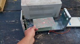
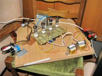
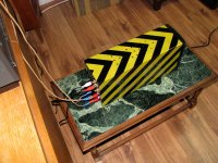
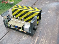
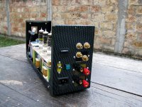
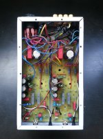
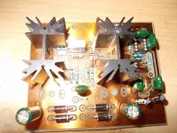
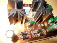
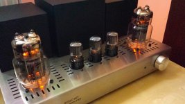
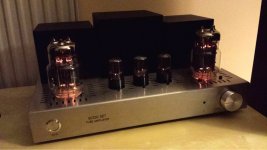
... "fun" variation of 13DR7 push-pull amp (schematic by Davorin).... OPTs are small visatons, not "the" best solution but for what I have heard so far - big bang for buck 🙂
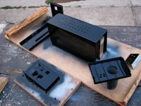
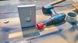
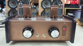
The case - old UPS, was sitting in the garage for a decade or so...
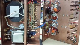
progress...
The case - old UPS, was sitting in the garage for a decade or so...
progress...
Attachments
-
 150807-DSC_1878.JPG113.1 KB · Views: 1,207
 -
 IMG_7489.JPG118 KB · Views: 503
 -
 IMG_7467.JPG170 KB · Views: 511
 -
 IMG_7445.JPG181.7 KB · Views: 468
 -
 IMG_7440.JPG181.7 KB · Views: 453
 -
 IMG_7419.JPG126.3 KB · Views: 1,124
 -
 IMG_7418.JPG142.4 KB · Views: 1,149
 -
 IMG_7369.JPG161.8 KB · Views: 1,172
 -
 150812-DSC_1896.JPG130.6 KB · Views: 1,182
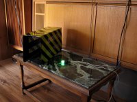
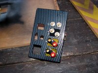
... and final result 😛
Attachments


I thought it looked familiar... 😀
wow 😎
I just couldnt put my finger on it, but now I see LOL
 .... gotta love ghostbusters (first movie)
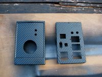
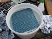
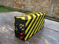
soundbrigade - in the bucket is a hydrographics film that has to be "hydrated" for short time before applying the activator and actually painting the piece... this was my first project I used that technique, and fake carbon was my first choice for trial/error - and after 10-15 tries and errors (on the scrap pieces), this is the result... not absolutely perfect (some of the lines warp a bit 😛) but in general - great way to put a pattern on the curved surface if you are *not* that good at airbrush LOL
there are many videos on tube how to do it (the main thing is - practice, practice and practice.... its all in the wrist (Duke Nukem) 😀
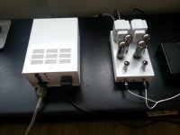
Which power plugs are those and where did you get them?My GU-48 (833A) project with separate PSU
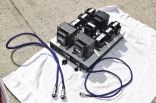
My Class A 6UGLC Push Pull 25W
Hi all,
this is my 2nd amplifier project (first with tubes) and it sounds GREAT!
This a Class A 6UGLC Push Pull 25W
the original schema is by novotone


The full story here :
Power supply part 1
Power supply part 2
Power supply part 3
Power Amplifier part 1
Power Amplifier part 2
Hi all,
this is my 2nd amplifier project (first with tubes) and it sounds GREAT!
This a Class A 6UGLC Push Pull 25W
the original schema is by novotone
The full story here :
Power supply part 1
Power supply part 2
Power supply part 3
Power Amplifier part 1
Power Amplifier part 2
Attachments

Last edited:
My GU-48 (833A) project with separate PSU
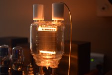
Very nice work....except that it is an electrocution death waiting to happen. You may live alone without pets, but what happens when the amp is in someone else's hands down the road? 😱
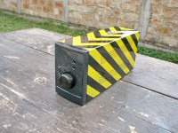
Looking at your diy filament terminals, it does not appear that the mount is capable of allowing the center to center distance between the 833A filament terminals to grow and shrink with temperature changes. If so, this will cost you in cracked tubes. I made that mistake once with a DIY 833A filament socket.
Last edited:
many to choose on ebay:Which power plugs are those and where did you get them?
Aviation Plug Disc Flange DF20 4 Pin XLR Ham Radio 20mm Panel Mount Waterproof | eBay
Very nice work....except that it is an electrocution death waiting to happen. You may live alone without pets, but what happens when the amp is in someone else's hands down the road? 😱
Looking at your diy filament terminals, it does not appear that the mount is capable of allowing the center to center distance between the 833A filament terminals to grow and shrink with temperature changes. If so, this will cost you in cracked tubes. I made that mistake once with a DIY 833A filament socket.
1.I need to replace top caps,they will cover the terminals fully.I have them just need to replace.
2.one of filament socket is fixed in round hole,other can move,because I made that hole bigger.
I leave it on sometimes for 8 hours,nothing goes wrong 😉
Very nice work....except that it is an electrocution death waiting to happen. You may live alone without pets, but what happens when the amp is in someone else's hands down the road? 😱
Looking at your diy filament terminals, it does not appear that the mount is capable of allowing the center to center distance between the 833A filament terminals to grow and shrink with temperature changes. If so, this will cost you in cracked tubes. I made that mistake once with a DIY 833A filament socket.
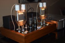
not dangerous anymore 🙂
Attachments
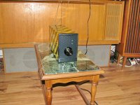
I am started on my loudspeaker measurement jigg, soldering it together now my nabure has move the high power wifi to a other place.
it is not ready yet I need some parts to get after holiday here is over.
It has a class B 10 watt amp to get a better movement of the speaker and resistor divider and zeners to protect the stuff connected to it.
regards
it is not ready yet I need some parts to get after holiday here is over.
It has a class B 10 watt amp to get a better movement of the speaker and resistor divider and zeners to protect the stuff connected to it.
regards
Attachments
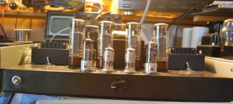
Swiss Cheese Special
Among my audio friends I am known as 'the EL34 guy', since I collected quite some of those over the years.
This summer however, I realised that I only have them sitting in boxes and in guitar amps.
So a 'need' was born 😀
With the absence of a budget, this was going to be a parts bin project, starting with the chassis: I have used, reused and abused this thing so many times that it is full of superfluous holes. Hence the name: Swiss Cheese Special 😎
Putting away the recent screen drive and other ss-assisted experiments, this had to be as classic as could be. So: no PCBs and as little silicon as possible.
If I had a socket for a AZ50 rectifier, I would probably have used it...
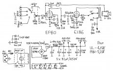
So here is the result: PP EL34 based on the Mullard 5-20 schematic.
Since I'm using quite less NFB than the original (10dB in triode, 12dB in UL) and source levels are a lot higher than 60 years ago, I put the input EF86 in triode and left out the cathode bypass cap to reduce the gain a bit. The ECC40 drivers have a lower mu than the original ECC83 as well.
As the PT only gives 2x300Vac, I used fixed bias to save the volts otherwise lost on the kathode resistors.
The amp puts out (just before clipping): 31W (pentode), 23W (UL) and 14W (triode).
Now it's time for listening and further tweaking
Among my audio friends I am known as 'the EL34 guy', since I collected quite some of those over the years.
This summer however, I realised that I only have them sitting in boxes and in guitar amps.
So a 'need' was born 😀
With the absence of a budget, this was going to be a parts bin project, starting with the chassis: I have used, reused and abused this thing so many times that it is full of superfluous holes. Hence the name: Swiss Cheese Special 😎
Putting away the recent screen drive and other ss-assisted experiments, this had to be as classic as could be. So: no PCBs and as little silicon as possible.
If I had a socket for a AZ50 rectifier, I would probably have used it...
So here is the result: PP EL34 based on the Mullard 5-20 schematic.
Since I'm using quite less NFB than the original (10dB in triode, 12dB in UL) and source levels are a lot higher than 60 years ago, I put the input EF86 in triode and left out the cathode bypass cap to reduce the gain a bit. The ECC40 drivers have a lower mu than the original ECC83 as well.
As the PT only gives 2x300Vac, I used fixed bias to save the volts otherwise lost on the kathode resistors.
The amp puts out (just before clipping): 31W (pentode), 23W (UL) and 14W (triode).
Now it's time for listening and further tweaking
Attachments
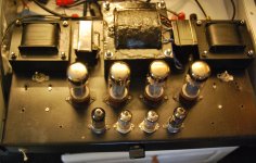
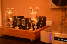
I would like to share my SET amp.
Pre: 12SL7 anode follower
Driver: 12SX7 srpp
Power: 6C33C with OPT
Sorry for poor quality photos. If there would be some interest I can make better photos and answer questions.
Pre: 12SL7 anode follower
Driver: 12SX7 srpp
Power: 6C33C with OPT
Sorry for poor quality photos. If there would be some interest I can make better photos and answer questions.
Attachments
- Home
- Amplifiers
- Tubes / Valves
- Photo Gallery