Can anyone confirm this?Perhaps it has to do with OPS topology being EF type or CFP type when it comes to 0.1-ohm Re safety-ness. If remembered correctly Cambridge Audio 840A has CFP output stage, so the bias spreader wouldn't care as much about what is going on with individual power transistor Vbe as it would in an EF type OPS.
It has loadsa bearing on bias stability so we need to put ...
O/P topology with Re, Rb, Thermal Design, PSU, Iq bla bla as important for xover as well as the release of Holy Smoke. 😱
______________________
Pics of da TAG McLaren stuff show very deluxe Thermal Design for the 250W @ 8R amps.
Thanks Guru Self for the pointer.
______________________
On another but related tag, can anyone with Self's 6th edition tell us if he did any more work on low level THD of EF vs CFP?
I think this was on page 131 of the 1st edition where his measurements show EF o/p THD was some 10dB better at 500mW HF than CFP though CFP was better at 25W.
Bob, this is something that you might want to check out too for your new book ... preferably in 'real life'. It is probably more important than 1pp zillion THD at 250W
_______________________
Alan, the reason for your inconsistent Iq is cos you didn't use Virgins to select and you didn't wash your devices in liquid BS. You thought I was joking didn't you 😀
While virgins are always in short supply, my DBLTs show liquid BS is a good substitute for the difficult-to-find, Unobtainium.
Perhaps it has to do with OPS topology being EF type or CFP type when it comes to 0.1-ohm Re safety-ness. If remembered correctly Cambridge Audio 840A has CFP output stage, so the bias spreader wouldn't care as much about what is going on with individual power transistor Vbe as it would in an EF type OPS.
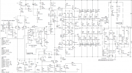
Nope. Attached is the 840W power amp schematic, is a classic double EF, not a CFP. Bottom right is the switchable class XD stuff. Also note the missing base stoppers, both for the power devices and the drivers. Output devices are 60MHz Sanken pairs. Also, in my opinion, driving 4 Sanken pairs with a MJE340/350 pair as driver is looking for driver SOA trouble.
It's against everything I've ever learned... but apparently it works. WTF do I know?
P.S. Power supply is +/-63V. Spec is 2x200W/8ohm, 2x350W/4ohm, 1x500W/8ohm mono bridged, 1x800W/4ohm mono bridged. Not sure if these watts are sine or "musical", the power supply suggests it's sine, but 800W/4ohm bridged is (IMO) a little bit of a stretch. It means 56Vrms in the 4 ohm load, 78Vpeak or about 20amps in the 4ohm load, 5amps per device. Sanken beta is 50 @ 5A, this is 0.4amps through the driver, add the driver bias and it's very close to the MJE340/350 low frequency Icmax of 0.5A. Looking at the MJE340/350 SOA curves in the data sheet, they cannot survive other than by luck, a kick lower bass will throw them into secondary breakdown.
Attachments
Last edited:
We'll call this a landmark design which proves the efficacy of Re=0R1 and confound Guru Cordell & other doubters 😱
A quick search for TAG McLaren schematics unearths only one for these august units.If you're interested in some of my designs, here is a sample of recent stuff:
...
TAG-McLaren 250x2R
TAG-McLaren 250x3R
TAG-McLaren 250MR
...
But I can assure you it's turtles, I mean 0R1 Re's, all the way down.
250W AMPLIFIER MODULE used in all 3 of the above. Issue 2 dtd 1/10/01 signed & checked DRGS.
3 pairs of o/p devices are used in EF2 with no Rb and Re = 0R22
GASP!??! 😱
... unless of course the dual resistor networks used are 2x0R11 in series. Anyone have one and willing to poke around with a multimeter?
Last edited:
I think this is dealt with by my post #6477 above.
It's not proof by assertion, it's proof by building lots of amplifiers.
Do you mean you don't know the theory behind it, it just work?
Thermal run away of my OPS
Hi
I powered up my OPS and set the default current. BUT I got into thermal run away as current went from about 0.6A total bias current to over 1.6A as it get hot. I turned it off at that point.
I use +/-31V rail with bench supply. Re=0.22ohm. No load, no IPS/VAS. I just use resistor to pull the bias spreader to +ve and -ve rail to turn the bias spreader to create the bias for the power transistors.
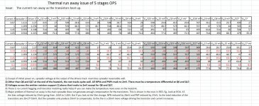
Attached is the JPEG copy of the excel file. The second table is where you want to look at. I am surprised I cannot attach the excel file.
1) First column is the voltage across the main bias spreader.
2) Second column is measure at the output of the driver pair right before the base stop resistors of the power transistor. This is the final voltage after the diamond pre-drivers and main drivers. You can see other than the initial turn on where everything in room temperature, it tracks the main bias spreader quite well.
3) I group the NPN, there voltages across the Re and PNP, there voltages across Re to give good comparison.
This is my analysis:
1) If you look at the Vbe of all NPN and PNP separately, 4 out of 5 track very well to 2mV. The Q6 and Q17 are at the extreme end and I kind of have a fan on even it's not blowing at the heatsink. But it is closer to Q6 and Q7. You can see at first turn on and even at 1A, all Vbe still track very well. Only when it started to run away then Q6 and Q7 start to fall off.
2) There is no current hogging and I contribute this to transistor matching. Even at high temperature, only Q6 and Q17 drop off, the other 4 pairs still sharing the load quite evenly. So absolutely no current hogging. I believe the transistor matching works.
3) The thermal run away is caused by the bias spreader that cannot produce enough compensation voltage for the power transistors. As explained in note #5 in the excel, when current goes from 1.45 to 1.65A, the bias spreader voltage reduced by only 33mV, BUT the Vbe of NPN and PNP together reduced by 53mV. this is where the problem is, that the current increase more and heat up more, and the bias spreader cannot follow even when the thermal coupling is good.
Please Help!!
If you look at the bias spreader voltage, it is only 1.1V instead of traditionally 1.4V. The resistors R10 and R18 for the multipler has to set up in the way you get only about -2mV/deg X(1 +1.1/1.4) and is way less than -4mV/deg C. so the more it heats up, the more it is off.
I don't know how to fix this as this is a diamond, the circuit only want 1.1V!!! I am using KSC3503, only thing I can think of is to change the to a transistor with higher tempco to get back the loss voltage. But transistor?
If anyone see anything in the file, please help me fixing this.
Moderator, if this is too off topic, please put me in my own thread. I started talking about the Re and thermal stability, so I put it here first.
Thanks
Hi
I powered up my OPS and set the default current. BUT I got into thermal run away as current went from about 0.6A total bias current to over 1.6A as it get hot. I turned it off at that point.
I use +/-31V rail with bench supply. Re=0.22ohm. No load, no IPS/VAS. I just use resistor to pull the bias spreader to +ve and -ve rail to turn the bias spreader to create the bias for the power transistors.
Attached is the JPEG copy of the excel file. The second table is where you want to look at. I am surprised I cannot attach the excel file.
1) First column is the voltage across the main bias spreader.
2) Second column is measure at the output of the driver pair right before the base stop resistors of the power transistor. This is the final voltage after the diamond pre-drivers and main drivers. You can see other than the initial turn on where everything in room temperature, it tracks the main bias spreader quite well.
3) I group the NPN, there voltages across the Re and PNP, there voltages across Re to give good comparison.
This is my analysis:
1) If you look at the Vbe of all NPN and PNP separately, 4 out of 5 track very well to 2mV. The Q6 and Q17 are at the extreme end and I kind of have a fan on even it's not blowing at the heatsink. But it is closer to Q6 and Q7. You can see at first turn on and even at 1A, all Vbe still track very well. Only when it started to run away then Q6 and Q7 start to fall off.
2) There is no current hogging and I contribute this to transistor matching. Even at high temperature, only Q6 and Q17 drop off, the other 4 pairs still sharing the load quite evenly. So absolutely no current hogging. I believe the transistor matching works.
3) The thermal run away is caused by the bias spreader that cannot produce enough compensation voltage for the power transistors. As explained in note #5 in the excel, when current goes from 1.45 to 1.65A, the bias spreader voltage reduced by only 33mV, BUT the Vbe of NPN and PNP together reduced by 53mV. this is where the problem is, that the current increase more and heat up more, and the bias spreader cannot follow even when the thermal coupling is good.
Please Help!!
If you look at the bias spreader voltage, it is only 1.1V instead of traditionally 1.4V. The resistors R10 and R18 for the multipler has to set up in the way you get only about -2mV/deg X(1 +1.1/1.4) and is way less than -4mV/deg C. so the more it heats up, the more it is off.
I don't know how to fix this as this is a diamond, the circuit only want 1.1V!!! I am using KSC3503, only thing I can think of is to change the to a transistor with higher tempco to get back the loss voltage. But transistor?
If anyone see anything in the file, please help me fixing this.
Moderator, if this is too off topic, please put me in my own thread. I started talking about the Re and thermal stability, so I put it here first.
Thanks
Attachments
Last edited:
Perhaps it has to do with OPS topology being EF type or CFP type when it comes to 0.1-ohm Re safety-ness. If remembered correctly Cambridge Audio 840A has CFP output stage, so the bias spreader wouldn't care as much about what is going on with individual power transistor Vbe as it would in an EF type OPS.
This is a very good point. The issue of bias stability in general is different for CFP vs. EF output stages. These differences may or may not extend to the issue of current hogging among multiple output pairs. Offhand, I don't know the answer as to whether a CFP topology would be less vulnerable to current hogging among multiple pairs. I am, however, thinking that a CFP is likely less vulnerable to thermal runaway in general.
Based on the material in his book, I would guess that most of Doug's production designs are CFP.
Cheers,
Bob
I have been thinking, the only way I can think of is to use a large transistor( or even the MJW1302/3281 for the bias spreader. If you look at the Vbe of those MJW, they are going way below 0.6V, at high temp, it's below 0.5V!!! This make the ratio of the two resistor( R10 and R18) to the point that it's way off the 2XVbe. But the complementary power transistor still have negative tempco of -4mV/deg, the only way is to use a transistor that has low Vbe so I can get more of the multiplier effect to get the tempco of the bias spreader back to -4mV/deg C.
I think I might need to more the bias spreader transistor to the middle of the power transistors to track the higher temperature transistors in the middle also.
Please help.
Thanks
I think I might need to more the bias spreader transistor to the middle of the power transistors to track the higher temperature transistors in the middle also.
Please help.
Thanks
Update on the bias spreader issue. I changed the spreader transistor to MJW NPN. I mounted on top of the middle transistor. I ran both 0.75A at 31V rails and 1A at 25V rails. I have been running for almost an hour. The current drop like 10% after I set it. It's getting very hot, not touchable anymore, but it's definitely seems stable. Seems like the choice of the transistor for the bias spreader is the KEY in this.
I have a suspicion if I just mount the MJW on top of Q17 at the end, I will eliminate the dropping of current because it is a little cooler and will eliminate the over compensation and keep the current constant.
I have to apologize for my negative view of the uP control method. Maybe there is some truth in getting away from this bias spreader. What I did not count on, is the Vbe which affect the tempco of the spreader make such a HUGE difference whether you get thermal run away ( not current hogging) with the amp. From my very limited experience of this, I need to match the Vbe of the bias spreader to the power transistor so I can get a full 2X multiplier to get the -4mV/deg C, or else, you cannot get the tempco right and you can run into trouble.
I really would like to hear from you guys that has a lot more experience about this. I really have not seen posts here OR even in books that mention how critical this issue is. You can design all the thermal manage in the world, you can match the transistor till the cows come home, if you don't have the same tempco between the spreader and transistors, you can get into thermal run away.....Or it can be opposite that you go from optimal bias to way under bias. It can go both ways.
I've been sweating on this the whole day. I am still testing, I'll update if anything new happens.
Last edited:
Maybe the manufacturer has to deliver parts with a predefined tolerance?
For mass production I would buy e.g. 1million pieces output stage power transistors with hFE 100 +/- 2% tolerance, same vbe and so on.
There would be no problem using 0.1R "without matching"... therefore no holy smoke ...
No he said unmatched devices, 5% resistors.
Jan
Also, when I pump frequency through the OPS, the current drop and wave form looked strange when I crank pass 1MHz. So something is not right. So I am taking everything back for now, pending more investigation.
Sorry.
This is not unexpected as far as I am concerned. 1 MHz is a very high frequency to expect any fidelity in such a stage. Almost all device parameters worsen at that frequency. Also, note that numbers like Ft are the frequency where the device gain is down to 1 - and you can imagine that performance worsens FAR before that.
Jan
...Attached is the 840W power amp schematic...
Also note the output transistors are the nice, low thermal resistance MT200 format.
I assume a similarly nice thermal insulator because it's an upmarket amp and I doubt they skimped.
Then calculated thermal loop return ratio is 0.5 to 0.6, no problem on that aspect.
Best wishes
David
Last edited:
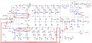
On pages 37 through 40 I discuss how I solved the thermal comp issue in my e-Amp here
http://hifisonix.com/wordpress/wp-content/uploads/2011/03/The_e-Amp_V2.03.pdf
Here I discuss thermal comp issue in more general terms
http://hifisonix.com/wordpress/wp-c...on-for-Audio-Amplifier-EF-Triples-V1.0231.pdf
http://hifisonix.com/wordpress/wp-content/uploads/2011/03/The_e-Amp_V2.03.pdf
Here I discuss thermal comp issue in more general terms
http://hifisonix.com/wordpress/wp-c...on-for-Audio-Amplifier-EF-Triples-V1.0231.pdf
Last edited:
Do you mean you don't know the theory behind it, it just work?
Alan, why say that about someone who designed 10's of amps and sold 10's of 1000's of them, and then in the same breath admit you yourself can't even get a Vbe spreader to work?
Why poison a thread like this?
Jan
Alan, why say that about someone who designed 10's of amps and sold 10's of 1000's of them, and then in the same breath admit you yourself can't even get a Vbe spreader to work?
Why poison a thread like this?
Jan
I think I got it to work changing the spreader transistor from KSC3503 to MJW big NPN. I am surprised I have not read about you have to match Vbe of the spreader with the transistor. From the long table I shown, you can see clearly where the problem lies. I use the MJW as spreader transistor, right now, it seems to work beautifully. It's not that the Vbe is important, it's because you have to set up the multiplier ratio. You need to get 2X -2mV/deg in order to compensate. If the Vbe of the spreader is too high, you have to adjust the resistor ratio so it is no where close to 2X. That's exactly the problem I have.
Theory does matter as it works, just like in this case. I don't believe in "just because it works". If there is a reason why it is safe with 0.1ohm without matching transistor, I am all ears on why. You have to pin point where the problem is before you can fix anything, not just try and true.
Now that I have proofed matching transistors really matters, that I get matching within 2mV on the Re for the same type and without current hogging of any sort with the 0.22, I am going to experiment lowering the Re and do the same thing soon.
FYI, I still don't buy that you can use 0.1ohm with no matching of transistors. If you have 5mV difference in Vbe or beta mismatch, you are going to have current hogging. Theory does matter. If it works, there got to be an explanation.
Last edited:
On pages 37 through 40 I discuss how I solved the thermal comp issue in my e-Amp here
http://hifisonix.com/wordpress/wp-content/uploads/2011/03/The_e-Amp_V2.03.pdf
Here I discuss thermal comp issue in more general terms
http://hifisonix.com/wordpress/wp-c...on-for-Audio-Amplifier-EF-Triples-V1.0231.pdf
Thanks, I am going to spend some time reading it.
One question. You use a MUR140 to prevent the VAS from saturation. I am doing the same thing using 1N4149 low capacitance diode. Yours are like 8 to 10pF. Do you have issue of increase distortion? The reason is the capacitance of the diode change with reverse voltage. The diode is acting like Miller capacitance, so you have variation of Loop Gain with the voltage swing. I am very interested what is your take on this.
Thanks
The MUR140's in my circuit are there as inductive fly back diodes across the output devices. The VAS anti-saturation diodes are BAV21. You need to use low capacitance diodes for the VAS anti saturation function.
The MUR140's in my circuit are there as inductive fly back diodes across the output devices. The VAS anti-saturation diodes are BAV21. You need to use low capacitance diodes for the VAS anti saturation function.
Thanks
BAV21 is 1.5pF vs 2pF of 1N4149. I have it on the digikey next order card already. I did simulation with and without the 1N4149, the 2nd and 3rd harmonic level definitely goes up about 7dB. I don't know whether it's important or not.
I am starting to read your compensation for EF article. I only read the first two pages, you hit it right on the nail for my case. I had to find it the hard way spending a few hours taking data and create the table to see the tempco is depending on the normal spreader adjustment. I still need to read more, but it's interesting you adjust the Rf to adjust the spreader voltage. I wonder if I set the R3 = R4 to get 2X -2mV/deg, can I adjust Rf to get the range for my amplifier? Then I just put the pot for R2.
I don't recall neither Self's or Mr. Cordell's book mention about this co dependency of bias voltage and tempco of spreader.
Thanks
Last edited:
Bob.
Firstly - many thanks for PA-Bible!
Second - please see table and comment:
...................Vds......Rds......Qg......Qgs.. ....Qgd.......Id........Ciss..........Coss
...IRFP9240....200......0,5.......44......7,1..... ...27........12.......1200.........370...
....IRFP240.....200.....0,18......70......13...... ...39........20.......1300.........400...
...IRFP9140....100......0,2.......61......14...... ...29........21.......1400.........590...
------
Alex.
FYI, I still don't buy that you can use 0.1ohm with no matching of transistors. If you have 5mV difference in Vbe or beta mismatch, you are going to have current hogging. Theory does matter.
Right. If theory says it can't work, and someone goes out and does it, that must mean that reality is somehow wrong. Thanks for clarifying that.
an
Right. If theory says it can't work, and someone goes out and does it, that must mean that reality is somehow wrong. Thanks for clarifying that.
an
I don't mean something is wrong, I think there is something missing that can explain that.
Remember Self wrote a book that he sell and want people to buy it. You expect a text book will give theory about why it works. I would not push this if Nelson Pass make this claim because he does not have a book that want to sell to people. He can use voodoo to make the amp sounds great for all I care. But you have to treat this differently if someone is selling a book to people. Just say it works because I made it work for 1000's of amp is just not good enough. There are books that are written by people that received Nobel price, they still need to explain why.
Last edited:
- Home
- Amplifiers
- Solid State
- Bob Cordell's Power amplifier book