I am scratching my head right now. I just tested my IPS/VAS board without OPS and only load driving is the 20K feedback resistor and the 10X scope probe. I use VFA with TMC of 18pF/1K/180pF. I have 2mA complementary IPS with active load, 14mA push pull VAS. I only get 500KHz large signal BW of 40Vpp, 40V/uS. Even small signal of less than 4Vpp is 900KHz.
I am not that brave to use TPC as I afraid of over shoot and ringing if not careful. With the safer TMC, I think I am pushing very hard already.
Only other thing is the 20K feedback resistor that can create a pole with the input capacitance. But I already have cascode in the LTP to eliminate the miller capacitance already. Seems like I am reaching the end of the road with the VFA. Only thing left is lower the feedback resistor to 10K and use 500ohm to get back gain of 21. But then I will have problem on the low cutoff frequency as I am using a 220uF cap for AC ground for the feed back.
Alan,
Is this a simulation or the prototype?
These kinds of questions are best investigated in simulation. If you simulate and play around, you can learn a lot. I recommend that you step back and start with conventional Miller compensation. Understand it thoroughly in both theory and simulation. Read Doug's or my book's sections on slew rate, and what determines it and what the tradeoffs are. These include input differential pair degeneration and Unity Gain Loop Bandwidth. Start with a conservative simulation with a 500kHz ULGF, check the gain and phase, kick the tires, and then move up to a higher frequency like 1MHz. Don't go above 1MHz until you have some experience and thorough understanding. Think less about aiming for the stars in performance and focus on solid understanding. One can get quite good performance with a Miller-compensated amplifier with 1 MHz ULGF.
You have also brought up another important point regarding impedance of the feedback network - the decoupling capacitor and its size. This is one area in which a DC servo can help a lot. It lets you go as low as you like in feedback network impedance without needing a huge electrolytic that may degrade the sound quality. In my MOSFET power amplifier, I think my feedback shunt resistor was only 215 ohms.
Cheers,
Bob
Perhaps its my rough Colonial view of Manners ... and I have never had tea with Liz II .. but I rather think I have been as polite as your good self. 🙂And perhaps you could do with some refreshment on the rules of Polite Discourse.
Just for the record, I do have a copy of Bode's book, and I have read it.
Can you say the same?
As a matter of fact I did have the same edition of Bode in my previous life circa 1980 and quoted some passages in a couple of AES papers to convince the unwashed masses that I kud reed en rite.
This Millenium, I have an electronic copy courtesy of Guru Zan and now pre10 2 unnerstan it 2
_______________________
But to get away from the "yus are all idiots & deaf dialogue" ...
I said earlier that this whole topic .. Oliver point, Iq, Re, Rb, PSU, Thermal design bla bla is so interrelated that the useful datapoints aren't more theoretical pontificating ... but 'real life'.
You have said ...
As you've built a zillion of these, your datapoint is more reliable than "virgins hand selected my output devices after washing in liquid BS and the ONE amp I've built is OK"I have used 0R1 as standard for a couple of decades, in amplifiers in serious mass production. Thermal stability has never been an issue.
As it happens I have a four-output-pair amplifier under detailed measurement at the moment. Re tolerance is 5%. No thermal stability issues whatsoever. The bias generator is naturally mounted on the top of one of the output devices.
Would you tell us a few more details? No need to give up all your secrets. Maybe just "This 4 output pair amp is like Fig X.X in my new book except its zillion W into 1/zillion ohms" good plug for da book
Then if you tell us what the commercial product is, someone might be tempted to buy one and perhaps take a pic of the Heatsink and give us a few more details like PSU etc. ... We'll call this a landmark design which proves the efficacy of Re=0R1 and confound Guru Cordell & other doubters 😱
Alan can build his design with 0R1 and if it releases the Holy Smoke, we know the safe limit is somewhere between the 2 designs/datapoints
I'm sure we can generate at least as much liquid BS over whether the Holy Smoke is contained by Rb, Oliver, Thermals, PSU bla bla ... But as this will be between 2 'real life' datapoints, we will have narrowed our search to more practical & useful limits.
...The real question is why we can't do the same thing with a VFA?...
How close can we get? I think the first part of this is to drive the VFA LTP with very low impedance on both sides... means a low-impedance feedback network on the feedback side and a capacitance to ground on the input side which will be part of the input LPF anyway (with the possible exception of a base resistor of small value if needed for stability)...
Thanks Bob, I came to the same conclusion when I tried it a while back, with results visible here> http://www.diyaudio.com/forums/solid-state/261973-middlebrook-gft-probe.html#post4076143
My initial motivation was to reduce the impedances to lower noise in an amplifier for some compression drivers, but the effect on speed was noticeable, exactly in accord with theory and the result very similar to Damir's CFA plot.
...impedance of the feedback network - ...capacitor and its size. This is one area in which a DC servo can help a lot....
One other solution is to use the complementary IPS and have no capacitor at all.
The excellent DC and thermal balance of the complementary halves should make it practical to cancel out the increased sensitivity due to the absence of the capacitor.
Still have to try this but it looks doable.
Best wishes
David
Alan,
Is this a simulation or the prototype?
These kinds of questions are best investigated in simulation. If you simulate and play around, you can learn a lot. I recommend that you step back and start with conventional Miller compensation. Understand it thoroughly in both theory and simulation. Read Doug's or my book's sections on slew rate, and what determines it and what the tradeoffs are. These include input differential pair degeneration and Unity Gain Loop Bandwidth. Start with a conservative simulation with a 500kHz ULGF, check the gain and phase, kick the tires, and then move up to a higher frequency like 1MHz. Don't go above 1MHz until you have some experience and thorough understanding. Think less about aiming for the stars in performance and focus on solid understanding. One can get quite good performance with a Miller-compensated amplifier with 1 MHz ULGF.
You have also brought up another important point regarding impedance of the feedback network - the decoupling capacitor and its size. This is one area in which a DC servo can help a lot. It lets you go as low as you like in feedback network impedance without needing a huge electrolytic that may degrade the sound quality. In my MOSFET power amplifier, I think my feedback shunt resistor was only 215 ohms.
Cheers,
Bob
Thanks Mr. Cordell.
This is the real circuit. Actually I pulled out the simulation I did months ago and it's the same.
I did more simulation. If I reduce the TMC to 4.7p/1K/47p, I got -3dB to about 3.5MHz without any peaking. My question to you is whether this sounds too good to be true?
Again, I have to order the NPO ceramic as I don't have it!!! More delay again. I do have some cheap Chinese ceramic caps I can try, but I cannot do distortion test though.
BTW, I did a lot of real circuit designs and testing on low noise VHF and UHF speed discrete circuit designs for years, so I am really not worry about having to take small steps on this. Turns out my observation is exactly the same as the LTSpice simulation.
Now that I bought the QA400 and learned how to use it, I think I am ready to move forward faster. I am going to power up the OPS as soon as I finish getting the freq. response up on the IPS/VAS. Hopefully it is as smooth as this one, then I'll be having an amp soon.
Thanks
Hi Mr. Cordell
I brought up the second IPS/VAS and use 5pF/1K/180pF TMC, I got the speed!!! I ran out of steam of my generator at 2MHz and still did not reach -3dB. I measure large signal and it swing 40V at under 0.3uS. That is over 120V/uS slew rate. I am happy camper. Just the IPS/VAS alone, it is very stable, no peaking of any sort. I use squarewave test to look for overshoot. There is no overshoot in 40V square wave, I decrease the amplitude down to less than 1V square, no overshoot at any amplitude. The waveform is rock solid, no sign of sensitivity or tweechyness that is typical of edge of stability.
Now the next step is to bring up the OPS and join them together and test with 4ohm load. I'll be happy camper if I can get the same result with -3dB at 2MHz. I don't think I need 3.5MHz.
Thanks
Hi dadod,
Thanks for presenting this plot. It does have remarkable loop gain at 20kHz, but it is not defying any laws of physics. If you drop off at 40dB/decade for 2+ decades, with a 5MHz ULGF, it all adds up and there is no magic.
The real question is why we can't do the same thing with a VFA? We can certainly shape the LG rolloff of a VFA pretty much the same way using TPC.
Put differently, is there less phase lag inherent in the CFA topology than in a VFA topology that has been designed with great care? We know they both share the same output stage, which is the big elephant in the room.
Where might the possible reduced phase lag come from in the CFA?
Looking at the feedback loop around the whole path, we see pretty much the same thing in the VAS and output stage. BUT the input stage is different. In a CFA the input stage looks more like a cascode to the feedback path, while in a VFA the input stage looks like a common emitter stage to the feedback loop. We normally think of a common base stage as being faster and with less phase lag than a common emitter stage.
I think the key question is whether, with careful design, we can make a VFA IPS as wideband (or low phase delay) as the IPS in a CFA as seen by the feedback path.
How close can we get? I think the first part of this is to drive the VFA LTP with very low impedance on both sides at high frequencies. This means a low-impedance feedback network on the feedback side and a capacitance to ground on the input side which will be part of the input LPF anyway (with the possible exception of a base resistor of small value if needed for stability).
That having been done, the next thing to do is to probably cascode the IPS and use fast, lower-voltage transistors in the IPS (breakdowns maybe <30V). But we also need to be aware that even the cascode transistors will add a bit of additional phase lag.
Cheers,
Bob
Hi Bob,
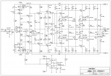
Thank you for your time. I attached the CFA schematic to show how it is quite simple, complementary IPS with supper pairs (Baxandall), enhanced VAS (EF VAS), and fast drivers same as used for the VAS.
I know there is not defying any laws of physics, and I know that I can manipulate a VFA to get similar Bode plot. I tried many VFA simulations (not with very low feedback impedance) but my CFA defeat a VFA by 20dB at 20kHz.
This IPS uses a resistor as a load and it works the best. I simulated with active load and in this case the loop gain increases at low frequencies, but the amp is nit easily compensated and more similar to a VFA and I dropped that approach.
A big advantage a VFA over CFA is no need for strict matching, in most cases CFA will need a servo, I think that CFA is not for a beginners.
Best wishes
Damir
Attachments
Last edited:
No, he specifically talked about using 0.1ohm for multiple pairs. He even gave examples of 3 output pairs with 0.1ohm. And that's scary. He insists on not doing any transistor hfe and Vbe matching also. That's unthinkable.
Well if he is doing that in production as he says, we must be missing something. I don't think he's making that up.
Jan
Well if he is doing that in production as he says, we must be missing something. I don't think he's making that up.
Jan
I powered up my 5 stages OPS without the IPS and VAS. I just use one resistor to pull the top of the bias spreader to +ve rail and bottom to -ve rail to turn on the bias spreader. I adjusted the current to about 220mA per stage. I am using 0.22ohm Re so the voltage across the Re is about 55mV to 60mV. This is like the idle current in real amp.
Bare in my, I did matched the Vbe to 1mV and matched hfe to better than 2%. I have 2.2ohm for base stop. I even run 3.5A current through the string of 0.22ohm and measure the voltage across the 0.22ohm resistors. I pick the ones that match within about 2mV. So I really have precision match on these 5 output stages.
The variation between the 5 NPN and 5 PNP, each kind has a spread of 5mV from say 55mV to 60mV. This is not what I expected. Much worst than I expected.
I have no explanation for this as I was so careful in matching them. From this observation, I don't know how you can be safe using 0.1ohm for parallel stages and run 216mA as suggested by Self in page 278. With 5mV variation in Oliver condition, this is 20% current variation ( 5mV variation of total 26mV across the Re). I can imagine the one with the most current will heat up enough that Vbe starts to decrease as it get hotter and draw more current.
I definitely will not lower the Re much lower than 0.22ohm from this observation. This is not good.
Can someone explain why I have so much variation after I hand match transistors and resistors?
You can see Self using 0.1ohm in Fig.9.19 in page 249. To be honest, until Self comes up with a theory and more proof than "I designed for so and so, you just have to take my word", I'll be very skeptical in his assertion. This is not just I have negative view on his book, this is from my own experiment here. It is playing with fire.
Last edited:
Well if he is doing that in production as he says, we must be missing something. I don't think he's making that up.
Jan
Maybe the manufacturer has to deliver parts with a predefined tolerance?
For mass production I would buy e.g. 1million pieces output stage power transistors with hFE 100 +/- 2% tolerance, same vbe and so on.
There would be no problem using 0.1R "without matching"... therefore no holy smoke ...
...
Can someone explain why I have so much variation after I hand match transistors and resistors?
...
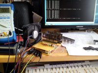
Use a fan during matching. Wait until devices have the same temperature.
Even touching the transitors for only 1 - 2 seconds will deliver completely different results. Room temperature should be stable too.
Attached a picture of my homebrew transistor matcher: Software starts with automated measurements and waits until values have stabilized.
Attachments
Alan.. My observation is that higher Re and also lower bias does not compromise performance. mind you that you take the Feedback after Re. I use 8 pairs and have been using up to 0.6 ohms (two ex 3ohm 2W metal strip).
The best Power-amplifier I have ever played on Shows or Private uses 0.68 Ohm Re. I can assure you nothing compromised there in terms of performance.
The way I have organised my OPS means that there's newer any switching spikes going back through the feedback network. I believe this is much more important than the last digit in steady state distortion.
I would not disagree with Doug that thousands of amplifiers he has designed have been built. Remember those designs would have had perhaps hundreds of design hours put into them to optimize i.a.o output stage bias, thermal tracking etc. Clearly he has also developed his temp comp methodology and a lot of associated knowledge around that. For an area as complicated as this, there is no substitute for spending a few years climbing the learning curve I am afraid. My comments about 0.1 Ohm Re resistors simply reflect my belief that the challenges get more difficult the lower you go - i.e you will need to invest significant effort to get a good result. And probably a whole lot more than that if you wanted to ensure good repeatable performance over thousands of units.
You are showing around 10 % variation in I quiescent at room temp. What's more important is that you have reasonable balance across the pairs over temperature.
Have you matched you base base stopper resistors? I assume Re's are also tightly matched. Are your Vbe's matched at the typical Iq current? Did you measure hFE at your typical Iq current? If you did it at a few mA or uA as you would do with a typical hFE tester, your figures will probably not reflect similarly at 100 mA Iq.
Last edited:
I powered up my 5 stages OPS without the IPS and VAS. I just use one resistor to pull the top of the bias spreader to +ve rail and bottom to -ve rail to turn on the bias spreader. I adjusted the current to about 220mA per stage. I am using 0.22ohm Re so the voltage across the Re is about 55mV to 60mV. This is like the idle current in real amp.
Bare in my, I did matched the Vbe to 1mV and matched hfe to better than 2%. I have 2.2ohm for base stop. I even run 3.5A current through the string of 0.22ohm and measure the voltage across the 0.22ohm resistors. I pick the ones that match within about 2mV. So I really have precision match on these 5 output stages.
The variation between the 5 NPN and 5 PNP, each kind has a spread of 5mV from say 55mV to 60mV. This is not what I expected. Much worst than I expected.
I have no explanation for this as I was so careful in matching them. From this observation, I don't know how you can be safe using 0.1ohm for parallel stages and run 216mA as suggested by Self in page 278. With 5mV variation in Oliver condition, this is 20% current variation ( 5mV variation of total 26mV across the Re). I can imagine the one with the most current will heat up enough that Vbe starts to decrease as it get hotter and draw more current.
I definitely will not lower the Re much lower than 0.22ohm from this observation. This is not good.
Can someone explain why I have so much variation after I hand match transistors and resistors?
You can see Self using 0.1ohm in Fig.9.19 in page 249. To be honest, until Self comes up with a theory and more proof than "I designed for so and so, you just have to take my word", I'll be very skeptical in his assertion. This is not just I have negative view on his book, this is from my own experiment here. It is playing with fire.
I might have to take it back. I had to change the resistor in the bias spreader to get lower than 220mA per stage. After I changed to get lower current, I only see about a little over 2mV variation of each kind. Also, when I pump frequency through the OPS, the current drop and wave form looked strange when I crank pass 1MHz. So something is not right. So I am taking everything back for now, pending more investigation.
Sorry.
I would not disagree with Doug that thousands of amplifiers he has designed have been built. Remember those designs would have had perhaps hundreds of design hours put into them to optimize i.a.o output stage bias, thermal tracking etc. Clearly he has also developed his temp comp methodology and a lot of associated knowledge around that. For an area as complicated as this, there is no substitute for spending a few years climbing the learning curve I am afraid. My comments about 0.1 Ohm Re resistors simply reflect my belief that the challenges get more difficult the lower you go - i.e you will need to invest significant effort to get a good result. And probably a whole lot more than that if you wanted to ensure good repeatable performance over thousands of units.
You are showing around 10 % variation in I quiescent at room temp. What's more important is that you have reasonable balance across the pairs over temperature.
Have you matched you base base stopper resistors? I assume Re's are also tightly matched. Are your Vbe's matched at the typical Iq current? Did you measure hFE at your typical Iq current? If you did it at a few mA or uA as you would do with a typical hFE tester, your figures will probably not reflect similarly at 100 mA Iq.
I have to investigate more. Yes, I match hfe at 200mA and pick to 2%. No, I did not match the base stop resistor. I had them on the board, it's too late to do that.
Right now I am testing Iq stability when heated up. Getting very late here, I am tired, that might contribute error on my part.
Please can you show a schematic of this TMC- without-OPS topology?...I just tested my IPS/VAS board without OPS and only load driving is the 20K feedback resistor and the 10X scope probe. I use VFA with TMC of 18pF/1K/180pF. I have 2mA complementary IPS with active load, 14mA push pull VAS...
If I'm not wrong you are using 1 pair of BJT OPS transistors in your designs, not 2, 3 or 4 pairs. In such a case 0R1 will give lower THD than 0R3. If you are using 2, 3 or 4 pairs you should increase RE.
S
But you are wrong.
The power amplifiers I have designed since 1993 cover the range from 1 to 4 output pairs. I also designed a 6-pair amplifier, but that never made it to mass production, for purely commercial reasons; there were no problems with thermal instability. All used 0R1 Re's.
You have said ... As you've built a zillion of these, your datapoint is more reliable than "virgins hand selected my output devices after washing in liquid BS and the ONE amp I've built is OK"
Would you tell us a few more details? No need to give up all your secrets. Maybe just "This 4 output pair amp is like Fig X.X in my new book except its zillion W into 1/zillion ohms" good plug for da book
Then if you tell us what the commercial product is, someone might be tempted to buy one and perhaps take a pic of the Heatsink and give us a few more details like PSU etc. ... We'll call this a landmark design which proves the efficacy of Re=0R1 and confound Guru Cordell & other doubters 😱
There really aren't any more details to give. It's all in Audio Power Amplifier Design , 6th edition.
If you're interested in some of my designs, here is a sample of recent stuff:
TAG-McLaren 100x2R
TAG-McLaren 250x2R
TAG-McLaren 250x3R
TAG-McLaren 250MR
TAG-McLaren 5x100R
Cambridge Audio 840A
Cambridge Audio 840E
Cambridge Audio 840W
Now that most of my work is on a consultancy basis, you'll appreciate that I can't divulge the name of my clients.
“You can understand,” said Holmes suavely, “that I extend to the affairs of my other clients the same secrecy which I promise to you in yours.”
But I can assure you it's turtles, I mean 0R1 Re's, all the way down.
It's just not good enough to say "I said so that 0.1ohm is safe". It just does not make sense.
I think this is dealt with by my post #6477 above.
It's not proof by assertion, it's proof by building lots of amplifiers.
Maybe the manufacturer has to deliver parts with a predefined tolerance?
No.
Perhaps it has to do with OPS topology being EF type or CFP type when it comes to 0.1-ohm Re safety-ness. If remembered correctly Cambridge Audio 840A has CFP output stage, so the bias spreader wouldn't care as much about what is going on with individual power transistor Vbe as it would in an EF type OPS.
- Home
- Amplifiers
- Solid State
- Bob Cordell's Power amplifier book