Want to spend more on your electric bills? Need a way to make a chipamp have much worse efficiency and lower output power? Attached schematic might help you achieve those goals 😀
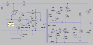
Basically a chipamp fed to a dual primary toroid transformer (24V to 110V+110V, 24v secondary as input from chipamp) driving totem-pole 6C33C output stage, wrapped in super-triode connected GNFB.
It gives you 16W output while dissipating about 220W for single channel. Maybe it's the 6C33C model i'm using but some say at Vg=0 and Vak=150v, 6C33C might give 2.5A current, which translates to 25W to 8 ohm.
Chipamp shown is OPA541 which is unity gain stable. You can, however, use the more ubiquitous LM1875 or TDA2030 family since the chipamp itself is making more than 24dB gain.
The toroid model is also still too perfect, with no winding resistance, inter-winding capacitance and leakage inductance. Main question is how stable it is, wrapping GNFB around such "inter-stage transformer".
Attaching the asc and inc (changed to txt) file, i am hoping someone with better skills in LTSpice could simulate a more real-life condition and check the stability.
Attachments
The maximum dissipation allowed in a 6C33C is 60W per tube. Therefore with your HT voltage the maximum allowable standing current is 0.4 Amp. This allows a maximum signal of 0.28 A RMS. The maximum power into 8 ohms is thus 0.63 Watts not 16W.
Totem pole and SRPP tube amplifiers require high impedance loudspeakers. For 2 x 6C33C, about 200 ohms would be right, ie 4 times Philips 800 ohm drivers in parallel, or 7 x 32 ohm drivers in series. Series operation requires driver matching. Cone resonance can vary +,- 10% or more, leading to poor control over resonance.
May I respectfully suggest you follow this advice I give to all newbies:-
1. Learn to read datasheets - undertand the impact of EVERY thing they list.
2. Forget SPICE simulations. Learn to do simple algrebra calculations with sensible approximations. Not only is this just as quick to do, you'll rapidly come to understand how circuits really work.
Newbies using SPICE is much like 1980's primary school kids who were allowed to use a 4-function calculator. Many ended up doing things like 24 x 31 and getting 7464 instead on 744. They made simple errors in keying that anybody could make, but because they had no experiince of working things out by hand, they did not recognise the answer as impossibly high, and they accepted what they got.
But just as a calculator is indespensible in adult life, SPICE is a valuable tool for electronic engineers who know from experience what they are doing.
Last edited:
You show an op-amp driving a transformer directly. This is bad practice. Inherent offset voltage in the op-amp inputs, amplified by the circuit configuration, will result in a heavy DC current in the transformer primary, saturating the transformer core and possibly overloading the op-amp.
What is tube U1 supposed to be for?
That 3-term regulator is a sitting duck.
Those 0.5 ohm resistors are not going to do anything. 6C33C has a gm of 40 ma/V. Therefore the impedance looking into the cathode cannot be less than 25 ohm.
The zobel network on the output is incorrectly sized. The idea of such networks is to make, as far as possible, the circuit see a resistive load at supersonic frequencies, and not the rising inductive impedance of the loudspeaker. Therefor the resistor should be the same as the loudspeaker rated impedance. This sort of network works better at improving stability if a choke is placed in series with the loudspeaker. The optimum capacitor size is then more independent of just what speaker you have connected.
Last edited:
Note that the 6C33C is reated for only 1000 hours of operation - a tiny fraction of the operational life of normal domestic audio tubes. With typical use 2 hours per day, the service life will be only be just a bit over 1 year.
I can only assume the Russians compromised the cathode design to secure high emission at the expense of lifetime.
I can only assume the Russians compromised the cathode design to secure high emission at the expense of lifetime.
Hi Keit!
Thanks for the input.
Totem Pole is what is on the output stage of Futterman OTL and there are quite a number of 6C33C-based OTL reaching claimed 16-25W. Look no further than our own forum here:
http://www.diyaudio.com/forums/tube...-dis-approval-otl-autobias-inv-futterman.html
http://www.diyaudio.com/forums/tubes-valves/189282-vacuum-tube-otl-power-amp.html
Those amps are not designed to run the 6C33C with the usual loadline where we stay within limits of max Power dissipation. Here we are idling at around half P-diss which is 30W (150V Vak @ 200mA) and will be subjecting the tubes to an almost vertical loadline (the load is the 8-ohm speaker). With that nearly vertical loadline, we are shooting way up to at Vg=0 where we expect to reach 2000-2500mA of current. Peak current of 2000mA equals 16W to 8R speakers. Sure we will greatly shorten the life of those tubes if we run sine wave through them constantly at 16W but music is not like that.
I won't argue if you state that OTL is abuse to tubes, especially with the low impedance speaker nowadays. This is probably the reason why we don't have many OTL tube amps. Those running OTL amps are probably ready to replace the tubes regularly.
It has to be power op-amp as the low inductance of the secondary winding will be asking lots of current.
More Super-Triode Amplifiers
I need to add that i miscalculated the power dissipation for each channel.
Heaters power dissipated for two 6C33C tubes is 12.6V x 6.6A = 83Watts
Plate idle dissipation is 30W x 2 6C33C triodes = 60Watts
Total is around 143Watts just for the OPS alone, not 220 Watts.
Thanks for the input.
Totem Pole is what is on the output stage of Futterman OTL and there are quite a number of 6C33C-based OTL reaching claimed 16-25W. Look no further than our own forum here:
http://www.diyaudio.com/forums/tube...-dis-approval-otl-autobias-inv-futterman.html
http://www.diyaudio.com/forums/tubes-valves/189282-vacuum-tube-otl-power-amp.html
Those amps are not designed to run the 6C33C with the usual loadline where we stay within limits of max Power dissipation. Here we are idling at around half P-diss which is 30W (150V Vak @ 200mA) and will be subjecting the tubes to an almost vertical loadline (the load is the 8-ohm speaker). With that nearly vertical loadline, we are shooting way up to at Vg=0 where we expect to reach 2000-2500mA of current. Peak current of 2000mA equals 16W to 8R speakers. Sure we will greatly shorten the life of those tubes if we run sine wave through them constantly at 16W but music is not like that.
I won't argue if you state that OTL is abuse to tubes, especially with the low impedance speaker nowadays. This is probably the reason why we don't have many OTL tube amps. Those running OTL amps are probably ready to replace the tubes regularly.
If what you state above is true, we will have many LM1875, LM3886 gainclone amp users with dead speakers piling up on their backyard. That OPA541 is a chipamp not unlike those used in gainclones. I use it in the simulation because that is what i have.You show an op-amp driving a transformer directly. This is bad practice. Inherent offset voltage in the op-amp inputs, amplified by the circuit configuration, will result in a heavy DC current in the transformer primary, saturating the transformer core and possibly overloading the op-amp.
It has to be power op-amp as the low inductance of the secondary winding will be asking lots of current.
It is the feedback part where we are feeding the negative input of the power opamp with signal mu times lower than the output signal going to the speaker. See here:What is tube U1 supposed to be for?
More Super-Triode Amplifiers
Yes, they are merely there to measure idle current on the actual circuit later.Those 0.5 ohm resistors are not going to do anything
I need to add that i miscalculated the power dissipation for each channel.
Heaters power dissipated for two 6C33C tubes is 12.6V x 6.6A = 83Watts
Plate idle dissipation is 30W x 2 6C33C triodes = 60Watts
Total is around 143Watts just for the OPS alone, not 220 Watts.
Attachments

Last edited:
"Chipamp shown is OPA541 which is unity gain stable. You can, however, use the more ubiquitous LM1875 or TDA2030 family since the chipamp itself is making more than 24dB gain."
Dear ballpencil,
Thank you for uploading the schematic and spice model. Can you also please upload the asy and inc file of any of the power op amp chip, I like to run the LTspice simulation for it. I have built totem pole otl amp, current model is 10 x 6c19p about equal to 2 x 6c33cb, give me 25W rms output.
Question:
The biggest problem with totem pole as compared to Circlotron type is additional demand for balance drive, and inter-stage transformer drive method is one of the solution. One don't have to use OP amp and can use 300B or any suitable tube you prefer, as there are such product already on the market. These OP amp have good sonic and so why not?
Hi Koonw..
See attached for the OPA541 model.
I decided on using Power op-amp instead of tubes simply for economical consideration. Whatever is driving the makeshift "interstage transformer" should be able to output 300-500mA of current to drive the low inductance 24V winding. Sure you can use proper tube input with interstage transformer with higher inductance but i bet they don't cost USD 16 with free shipping
5VA Toroidal Voltage Transformers Audio Transformer Dual 110V 115V120V 50 60Hz | eBay
Attachments
You show an op-amp driving a transformer directly. This is bad practice. Inherent offset voltage in the op-amp inputs, amplified by the circuit configuration, will result in a heavy DC current in the transformer primary, saturating the transformer core and possibly overloading the op-amp.
Ah sorry i didn't read this part properly.
There is no offset voltage in the op-amp inputs, thus no offset on the output. The negative input is tied to the output via 100k resistor to check the output offset while the positive input is tied to ground.
You are correct on the zobel network. I mistyped 10R to 100R.
That 3-term regulator is wired as Constant Current Sink of around 10mA.
Last edited:
Member
Joined 2009
Paid Member
Hmm....
Seems a bit of a daft idea--To make an OTL--Then bung a Transformer (probably quite an expensive one) right in the middle of it!
As to the life and the max current a 6C33 can handle, They will pass on music peaks well over 4A and do that for years on end, regardless of previous comments......
6C33 Reliability is NOT a problem if they are treated properly.
Tube failures are nearly Always because they haven't been burned in properly--They need a good few hours (6+) to be considered burned in before they are used anywhere near full power....
Failure to do so, will result in arc-over and tube (plus possibly speaker if not protected) destruction.
IF you ever have a 6C33 arc over--Destroy it, Never use it again as it will arc again.
Personally, I prefer the Inverted Futterman/Technics circuit for the 6C33C OTL.
Totem-pole/simple single ended pushpull configuration with separate phase splitter--in your case, transformer-- the upper tube works as a cathode follower and the lower tube works as a standard grounded cathode amplifier stage, the tubes will have different output impedance and distortion will be introduced if the amplifier is driven hard......
Note that the 6C33C is reated for only 1000 hours of operation - a tiny fraction of the operational life of normal domestic audio tubes. With typical use 2 hours per day, the service life will be only be just a bit over 1 year.
I can only assume the Russians compromised the cathode design to secure high emission at the expense of lifetime.
i have a 6C33 set running close to 4 years now and no signs of slowing down....
it is used on a daily basis....i run both cathodes at about 40 watts plate...
So, you are running the output stage in Class B then. A tube Class B amp - Yuck. The dissadvantage of a solid state amp without the advantages.Here we are idling at around half P-diss which is 30W (150V Vak @ 200mA)
The reason why OTL is rare is because only one company, Philips, was game enough to make 400 ohm and 800 ohm speakers in volume. The high impedance leads to very thin wire, and a delicate voice coil prone to failure. And as the operating voltage is high, the wire enamel must be of a high standard, an it must be a greater fraction of the voice coil volume anyway. This makes high impedance speakers inefficient.I won't argue if you state that OTL is abuse to tubes, especially with the low impedance speaker nowadays. This is probably the reason why we don't have many OTL tube amps.
No, because they are feeding loudspeakers. A loudspeaker has a DC resistance about the same as its rated impedance. In the 1950's, when spekaers were more efficient, a typical 8 ohm speaker had a DC resistance of around 6.4 ohms. Today's speakers are built for better sound quality and not efficiency. Their DC resistance is closer to the nominal impedance.If what you state above is true, we will have many LM1875, LM3886 gainclone amp users with dead speakers piling up on their backyard.
But you are taking the output of an op amp direct into a transformer winding, in which we can expect a vary low DC resistance, so a much greater DC current.
That's not what your circuit shows.It is the feedback part where we are feeding the negative input of the power opamp with signal mu times lower than the output signal going to the speaker.
Julius Futterman....not that i plan to go OTL route ever...
atmasphere: Atma-Sphere
and so on and so forth....
An externally hosted image should be here but it was not working when we last tested it.
atmasphere: Atma-Sphere
and so on and so forth....
Note that the 6C33C is reated for only 1000 hours of operation - a tiny fraction of the operational life of normal domestic audio tubes. With typical use 2 hours per day, the service life will be only be just a bit over 1 year.
I can only assume the Russians compromised the cathode design to secure high emission at the expense of lifetime.
Err--Not quite.....
The quoted Life is a Guaranteed life where current and transconductance is will still conform to that listed in the data-sheet at the end of 1000 hours time at rated, with only a 10% failure rate.😉
Not many Western tube makers guaranteed to this extent, as they were Profit driven. Russian tube makers had no such drawback, they did not comply with the notion of 'Planned Obsolescence' as western makers did/do.
Proper Russian Military tubes are probably some of the best ever made in my opinion.🙂
Don't be ridiculous.
Western consumer tubes were far far better than that. If 10% failure was allowed after only 1000 hours, vacuum tube TV sets would not have been practical. The average TV contained about 20 vacuum tubes, many of which were triode-pentodes ie two tubes in one. Most housewives left TV's running all day while they did the housework, and as a means of occupying small children. Then the same TV's were used as evening entertainment. So about 10 hours per day - about 3500 hours per year
On your figures, TV's should have had about one tube failure every month. Never happened. Most TV's ran 5 years or more without any failure. And then typical failures were typically dry/dirty contacts in the tuner, noisy volume controls, failed electrolytics. Not just tubes.
The emission in the 6C33C is very high for a tube rated at only 60 watts dissipation, and in an envelope that size. The 6C33C is rated for a max cathode current of 600 mA. A KT88 (42W dissipation) can only be used up to 230 mA. And yet the 6C33C has a 300V heater-cathode voltage rating to support its intended role as a power regulator. Thus I suspect that the Russians did indeed compromise service life to get that level of emission. Probably added a rather large amount of calcium in the cathode alloy - that will do it. Or added some radioactive substance as was done in some low heater current American tubes at the end of the tube era.
Last edited:
That's not what your circuit shows.
This is the main idea.
An externally hosted image should be here but it was not working when we last tested it.
The output gets fed to the plate and comes out from the cathode attenuated mu-times lower.
The difference is that my input signal goes to the non-inverting pin.
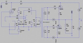
Below is the more conventional inverted Futterman OTL. I dislike this version for few reasons:
1. The need for another higher supply +350V
2. Heater power elevation for the cathodyne is required
3. Since 6C33C varies wildly between each tubes, matched pair are very unlikely found and DC servo is needed to keep the output offset minimum. Hence another need for bipolar supply for DC servo op-amp. Now, i thought, why not use this bipolar supply for the input/driver also.
An externally hosted image should be here but it was not working when we last tested it.
The output gets fed to the plate and comes out from the cathode attenuated mu-times lower.
Note that in John's circuit, the cathode is feeding a virtual ground, so its AC voltage is essentially zero.
SY,
Do you mean the attenuated signal gets sunk to ground?
It is a CCS on the cathode, doesn't it mean that point is high impedance? Cathode would move along with the signal since the CCS is trying to maintain constant current.
Do you mean the attenuated signal gets sunk to ground?
It is a CCS on the cathode, doesn't it mean that point is high impedance? Cathode would move along with the signal since the CCS is trying to maintain constant current.
The opamp provides a virtual ground, acting as an I to V converter. The actual AC voltage at the input is essentially zero. Remember, in the limit of infinite gain, the two input terminals of the opamp must be at the same potential. So the CCS doesn't change that, it just means that current variations through the tube are translated (more or less) exactly into current variations into the virtual ground, which are then translated exactly into voltage variations at the opamp output. The feedback resistor determines the transformation ratio of amps to volts.
- Status
- Not open for further replies.
- Home
- Amplifiers
- Tubes / Valves
- Another Approach to Totem Pole OTL Amplifier