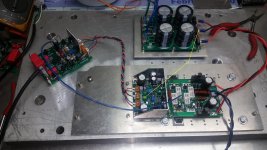
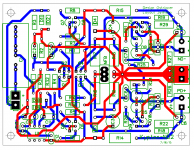
I took a break from the DAC and assembled a set of boards. My tester output board is getting rough. The zobel resistor smokes badly above 50kHz but the input seems flawless. No listening test yet but the board layout seems good. I'll shuffle some parts around a bit and touch up the silk screen, then send the files to Evan.
Attachments
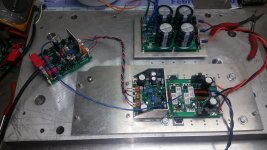
What IPS used?I took a break from the DAC and assembled a set of boards. My tester output board is getting rough. The zobel resistor smokes badly above 50kHz but the input seems flawless. No listening test yet but the board layout seems good. I'll shuffle some parts around a bit and touch up the silk screen, then send the files to Evan.
Edit:Now i see,Kypton ND.
I can't see G2 to star GND.
Attachments
Last edited:
JW ans OS,
A question concerning a mini slew. If you built the mini slew and reduced its size what about the output device spacing on a vertical mounted heat sink. What would be optimum with the device spacing, would you try and space the two pair boards so the outputs would be on opposite ends like you have now done by spacing the 5 pairs boards? I'm just thinking about how to best optimize the layout of the vertical heat sink with one two pairs or even a three pairs board and a single pair board over the vertical distance. I even have the crazy idea of a biamp board where the small amp would be in the center and the other amp would be around that amp with the output devices on opposite sides of the center amp section. Perhaps I am just thinking to hard here an making things overly complex.
A question concerning a mini slew. If you built the mini slew and reduced its size what about the output device spacing on a vertical mounted heat sink. What would be optimum with the device spacing, would you try and space the two pair boards so the outputs would be on opposite ends like you have now done by spacing the 5 pairs boards? I'm just thinking about how to best optimize the layout of the vertical heat sink with one two pairs or even a three pairs board and a single pair board over the vertical distance. I even have the crazy idea of a biamp board where the small amp would be in the center and the other amp would be around that amp with the output devices on opposite sides of the center amp section. Perhaps I am just thinking to hard here an making things overly complex.
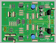
G2 is under the board.What IPS used?
Edit:Now i see,Kypton ND.
I can't see G2 to star GND.
G2 is under the board.
In this case it isn't connected to star gnd.
Just in case..
JW ans OS,
A question concerning a mini slew. If you built the mini slew and reduced its size what about the output device spacing on a vertical mounted heat sink. What would be optimum with the device spacing, would you try and space the two pair boards so the outputs would be on opposite ends like you have now done by spacing the 5 pairs boards? I'm just thinking about how to best optimize the layout of the vertical heat sink with one two pairs or even a three pairs board and a single pair board over the vertical distance. I even have the crazy idea of a biamp board where the small amp would be in the center and the other amp would be around that amp with the output devices on opposite sides of the center amp section. Perhaps I am just thinking to hard here an making things overly complex.
On a two pair board, you would want the output devices fairly close together so the temperature would be the same. You would need to try to make the lower devices not cool quite as well also.
In this case it isn't connected to star gnd.
Just in case..
G2 connects to either end of the output board. I didn't run a separate one back to the star. The heat sink is grounded through my bench top. I didn't bother to chassis ground the star ground for this test though. I just wanted to verify the layout was correct.
In all my test G2 & speaker return connected directly on star GND.G2 connects to either end of the output board. I didn't run a separate one back to the star. The heat sink is grounded through my bench top. I didn't bother to chassis ground the star ground for this test though. I just wanted to verify the layout was correct.
My heat sink never connected ,open frame😀
In all my test G2 & speaker return connected directly on star GND.
My heat sink never connected ,open frame😀
That's how I did my finished amplifier too. This one is connected the way Jason recommended. There's a couple different theories on how the speaker returns should be run. Some say they should return to the amp board and back to the supply with the rail feeds.
If you guys want I could have the ND boards produced and distribute them to members who want them.
Evan
yes please

I'm in to but first need to be tested and compared with some earlier version IPS.
Thimios and Still4given tested this a couple months ago.
I'm in to but first need to be tested and compared with some earlier version IPS.
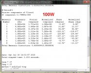
It was tested with the sweetest clip and square wave results.
It's "weak point" is >100db PSRR versus a spook or wolverine >120db.
Servo and 20hz THD is also <1ppm - It should be very good for LF SQ.
(below) are it's strong point(s). Unmatched low THD with the right combo
of feedback and compensation values.
The IPS layout would most likely make for those last parts per million.
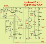
(Jeff !!!! ) ... Edit - show the tracks ....
OS
Attachments

Last edited:
It was tested with the sweetest clip and square wave results.
It's "weak point" is >100db PSRR versus a spook or wolverine >120db.
Servo and 20hz THD is also <1ppm - It should be very good for LF SQ.
(below) are it's strong point(s). Unmatched low THD with the right combo
of feedback and compensation values.
The IPS layout would most likely make for those last parts per million.
(Jeff !!!! ) ... Edit - show the tracks ....
OS
I'll send you the files. It's tough to see in pictures.
Thimios and Still4given tested this a couple months ago.
Where can be find their test report (more interested on sound than technical area) of course these two usually hand in hand...🙂
I can't think of any changes besides fiddlin' with R18/19 to get the right
Ivas. Ivas can also be adjusted by R4/7.
C3/4 could be larger/smaller , as long as some reasonable value is there
(22-100uf).
Current feedback network could have a different value to a degree ,
if the 25:1 ratio is heeded. The 2 main compensation caps could also
be 22-47pf.
Any combination of these tweaks would just make "perfect" slightly more
or less "perfect". This IPS even has a wider tolerance than a symetri
or spooky. The last posted schema is 2-7ppm 20K - this IPS matches
the wolverine !!
OS
Hi Pete,
Is this the latest schematic?
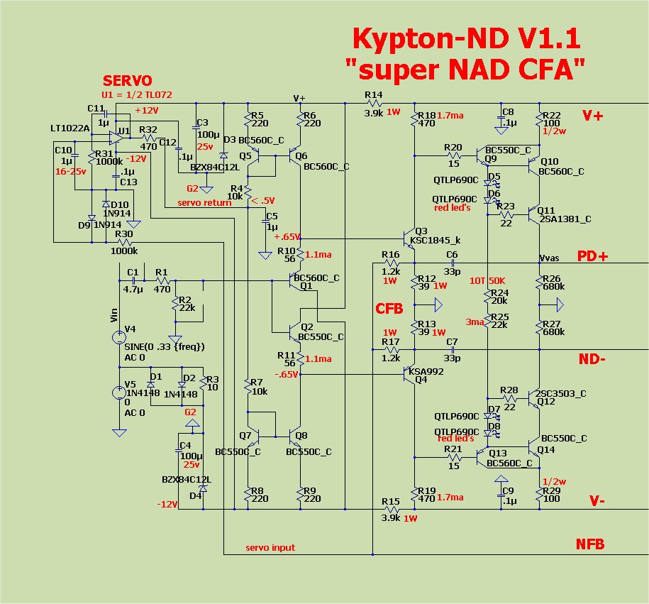
Damn close ...
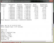
(Below) What I just got all <10ppm out of.
R18/19 might still need changes to get within the 5.3ma Ivas target.
If you get within 2ma of that , R24 should get you the rest of the way.
8-9ma on R22 will give a perfect 5-5.5ma output.
Thimios had no overshoot on C6/7= 33pf , 22-27p might be possible.
An amp like this would be >350v/us !
OS
Attachments
- Home
- Amplifiers
- Solid State
- Slewmaster - CFA vs. VFA "Rumble"