I`m at digikeys website,but I dont know the english word for a mainscable that have a mains plug allready mounted on it..sort of.. 🙂
AC7-DK CUI Inc | T100-DK-ND | DigiKey
Found this one but you will need to cut off the second plug. Remember: you need a power cord with PE.
Found this one but you will need to cut off the second plug. Remember: you need a power cord with PE.
A reply to jean-paul
jean-paul asked some questions in the group buy thread & I've taken the liberty of posting my belated replies here
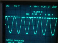
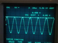
AC input from the TRIAD transformer is 6.25VAC with a roughly 2 ampere load.
Attached are images of the loaded and unloaded condition - please disregard the flattops on AC waveform, they're caused by the pretty aggressive IEC input filter I'm using on the 110VAC line.
Noted the unusual name for the heatsink vendor, wasn't sure if it was an appellation or a statement of preference - but declined to do further research....
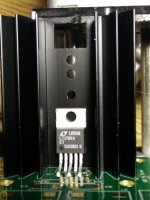
As originally installed, most of the 1764's metal tab was on the heatsink, but part of its plastic body was exposed through the notch in the heatsink.
This didn't seem like an issue, since the heat stress at 2 amps appears quite low, but in the interest of completeness, here's a way to modify the Assmann V8813Y heatsink to properly mount the LT1764:
First - loosely mount the LT1764, make sure that it's fully seated, and its back is perpendicular to the board.
Then turn the heatsink over so that its mounting pins are sticking up, and then gently slide it to meet the LT1764's back - check and make sure that the sink is aligned with the outline drawn on the board.
Now use a fine-point magic marker to outline the mount hole - remove the sink and drill with an M4 or #22 drill and it should fit without stress - attached is a photo showing the IC and reversed sink on a bar board ready to mark.
If you're concerned about niceties, it's easy to clip or grind away the unused mount pins, and a milled or filed 2MM slot in the bottom will allow cool air to reach the IC's pins.
Cheers
Jim
jean-paul asked some questions in the group buy thread & I've taken the liberty of posting my belated replies here
AC input from the TRIAD transformer is 6.85VAC unloaded with 114VAC line voltage.Some questions:
1. Since you have built it as the first could you please observe input voltage on an oscilloscope preferably with a high load ?
AC input from the TRIAD transformer is 6.25VAC with a roughly 2 ampere load.
Attached are images of the loaded and unloaded condition - please disregard the flattops on AC waveform, they're caused by the pretty aggressive IEC input filter I'm using on the 110VAC line.
2. Is IC1's back fully covered by the Assman (what's in a name ?) heatsink ? It seems not, but it needs to be to transport heat the best way.
Noted the unusual name for the heatsink vendor, wasn't sure if it was an appellation or a statement of preference - but declined to do further research....
As originally installed, most of the 1764's metal tab was on the heatsink, but part of its plastic body was exposed through the notch in the heatsink.
This didn't seem like an issue, since the heat stress at 2 amps appears quite low, but in the interest of completeness, here's a way to modify the Assmann V8813Y heatsink to properly mount the LT1764:
First - loosely mount the LT1764, make sure that it's fully seated, and its back is perpendicular to the board.
Then turn the heatsink over so that its mounting pins are sticking up, and then gently slide it to meet the LT1764's back - check and make sure that the sink is aligned with the outline drawn on the board.
Now use a fine-point magic marker to outline the mount hole - remove the sink and drill with an M4 or #22 drill and it should fit without stress - attached is a photo showing the IC and reversed sink on a bar board ready to mark.
If you're concerned about niceties, it's easy to clip or grind away the unused mount pins, and a milled or filed 2MM slot in the bottom will allow cool air to reach the IC's pins.
Hopefully this should answer most questions for non-EU builders.3. A picture would be nice.
Cheers
Jim
Attachments

Last edited:
NICE!
It looks like the Triad will work just fine.
I had not noticed the deeper notch in some of the heatsinks. Great fix.
Other alternatives in the US are;
digikey - Aavid Thermalloy 530002B02500G which has a notch that looks OK in the picture
or
Newark - AAVID THERMALLOY 529902B02500G that looks like a small notch
It looks like the Assmann heatsink that Jim has is no longer in stock.
Jac
part number correction
It might be FAR more useful if I'd post the correct part number:
The heatsink in question really is an Assmann V8511Y - Digikey part # AE10880-ND:
V8511Y Assmann WSW Components | AE10880-ND | DigiKey
SIGH!

Oh well, like they say when you get fired from the Swedish Deviled-Egg factory:
"Chuck 'em if they can't flake a yolk ...
Cheers
Jim
NICE!
It looks like the Triad will work just fine.
I had not noticed the deeper notch in some of the heatsinks. Great fix.
Other alternatives in the US are;
digikey - Aavid Thermalloy 530002B02500G which has a notch that looks OK in the picture
or
Newark - AAVID THERMALLOY 529902B02500G that looks like a small notch
It looks like the Assmann heatsink that Jim has is no longer in stock.
Jac
It might be FAR more useful if I'd post the correct part number:
The heatsink in question really is an Assmann V8511Y - Digikey part # AE10880-ND:
V8511Y Assmann WSW Components | AE10880-ND | DigiKey
SIGH!
Oh well, like they say when you get fired from the Swedish Deviled-Egg factory:
"Chuck 'em if they can't flake a yolk ...
Cheers
Jim
The Aavid Thermalloy 530002B02500G seems a better choice compared with the Assmann V8511Y as far as i can tell. At least it can be soldered with its original pins and it does not have to be used upside down 🙂 Best would be the Fischer SK129 as per BOM.
Are there any other builders that have the PSU ready/in use ?
Are there any other builders that have the PSU ready/in use ?
Last edited:
The Aavid Thermalloy 530002B02500G seems a better choice compared with the Assmann V8511Y as far as i can tell. At least it can be soldered with its original pins and it does not have to be used upside down 🙂 Best would be the Fischer SK129 as per BOM.
Are there any other builders that have the PSU ready/in use ?
Sadly, the Fischer heatsink isn't easy to find over here, Newark will sell you one with 4 weeks delivery + $20 shipping - which is fairly stiff, even for audio jewelry.
Arrow Electronics claims to have the Fischer in stock at a reasonable price, they also have the 47uF tantalum caps, 700 ohm chokes, and the LT1764AET-PBF regulator at pretty competitive prices. OTOH they have neither the TRIAD transformer nor the Panasonic cap available.
The Thermalloy 530002B02500G is in stock at Digikey (530002B02500G Aavid Thermalloy | HS380-ND | DigiKey) and looks like a much better bet than the Assmann for North American builders.
Jim
Most of the parts arrived from Digikey today, just four days from the USA including the weekend. I still need the heatsink and a few other bits but fortunately Farnell are having a shipping free on any size of order promotion until the end of July. But they're a little cheaper at Rapid anyway...
My words those SMD resistors are small though, I can barely see them. Any advice on how to make a good job of soldering them? The first challenge looks to be to "secure" them to the pcb before soldering, not easy when they're so small. And then use a fine tip, a large magnifying glass and a steady hand!
My words those SMD resistors are small though, I can barely see them. Any advice on how to make a good job of soldering them? The first challenge looks to be to "secure" them to the pcb before soldering, not easy when they're so small. And then use a fine tip, a large magnifying glass and a steady hand!
For those that feel uncomfortable with SMD 0805 parts I added pads for through hole resistors...but it is OK to learn to work with SMD. You will have to as through hole parts will be out of production anytime soon. Too bad, I liked cap rolling 😉
*It is either the SMD setting resistors OR the through hole parts, don't use both ! You can mix though but I miss the point there 🙂
Soldering the SMD resistors: please use a tiny amount of solder on one of the pads. Place the part with tweezers and heat the presoldered pad. Try to position the part while heating the solder. When the solder is becoming fluid you can put the part in the right position. When it is done heat the joint and press the part against the board (I do this with my fingernail) otherwise it will be soldered with an angle on the PCB. Now solder the other pad. Excess solder can be removed with desoldering braid. Common mistake is to have a too large soldering area on one side and a too short side at the other. The part must be right in the middle for best results. After a while you get the hang of it.
Many like the use of extra flux. I can't tell as I never tried.
Last edited:
Thanks jean-paul, that makes sense. I guess the resistors are too small to tin first, but it should be an interesting experience.
I traced the circuit out BTW, both interesting and educational. Nice work 🙂.
I traced the circuit out BTW, both interesting and educational. Nice work 🙂.
Video
Here is a video showing fairly clearly how to manage soldering SMD components by hand. I have had success with Dario's method. The tacky flux is very helpful. I also am prone to making mistakes, so solder wick and low temp solder (for example, Chip Quik SMD rework alloy) can be saviors if you make a mistake.
https://www.youtube.com/watch?feature=player_detailpage&v=HPOr1yalH6Q
Of course, it is not the only good method, it is just the one I learned.
Jac
SMT soldering
I'm not an expert at smt soldering, but my recommendation would be to get a cheap hot air soldering gun if you are doing occasional smt soldering. Get some solder paste, don't worry about the paste getting off the pads or the parts not being perfectly aligned, when you apply the hot air the solder will migrate off the mask into the pads and the tension will straighten the parts (of course, both within limits...). If you use water based solder paste you can just wash the pcb under the faucet with a soft toothbrush (assuming the pcb does not have any parts that you are not supposed to get wet). Or you can get no-clean paste and don't clean at all. If you get a heat gun, do the smt parts first, then the through the hole ones. Hand soldering gets difficult when the smt parts get very small. Using a peelable solder mask like Wondermask (look it up in Mouser) and a hot air gun you can rework your smt components very easily without disturbing the ones you don't want to remove (use a small diameter nozzle on the hot air gun for removing single or closely spaced smt parts).
You still need some kind of magnification to check the soldering after you are done, especially if you have smt chips with close together pins (checking for solder bridges for example)..
Thanks for the replies - the video was fascinating. As a valve man even the through hole resistors look alarmingly small so I think I'm going to have some fun with this! I'll give jean-paul's method a go first but I might need some finer solder. There's remarkably little used in the video.
Thanks for the replies - the video was fascinating. As a valve man even the through hole resistors look alarmingly small so I think I'm going to have some fun with this! I'll give jean-paul's method a go first but I might need some finer solder. There's remarkably little used in the video.
Solder diameter of 0.020 inches or 0.508 mm are what I am using for surface mount work. If you don't have small diameter available, you can control the amount of solder by how much you put on the tip of the iron, using the method in the video. Using J-P's method, you could also put the solder on the tip, then on the pad, in theory. I haven't tried this way. The trouble with putting the solder on the iron's tip is that you need a bit of flux on the joint because you have burned off the flux in the solder before it reaches the joint.
As Palmito says, you will benefit from good magnification (and lighting), both for doing the soldering and for inspection. I use a magnifying glass for soldering (power = 2x,?) and a gem loupe (10x).
I can't say that my joints always look as good as required in this document, but it is interesting to see how they should look in this link.
http://www.ipctraining.org/demos/pdf/drm-smt-e.pdf
As for solder composition, that's a question to flame any forum, so I will avoid it other than to say that I haven't changed the type of solder that I like just because it is small diameter or because I am soldering surface mount components.
Have fun.
Jac
I made a start this evening, most of the larger SMD components were okay to solder. The small resistors were a bit fiddly and wasn't made any easier as the only solder I had to hand was 0.7mm dia/22swg. They're not pretty but are okay according to my meter. I'd definitely use thinner solder next time (if I could wait). I'd also get some better tweezers - mine are too pliant (cheap!).
I think I would have struggled without advice though, so thanks again.
I found the trickiest job was soldering C8, probably because of it's square cross section which made it a bit unstable. It also seemed to pass heat from the iron to the other pad very quickly, so when I thought it was okay to get a good joint it moved as the other end was fluid. Practise makes perfect I guess. I don't think it helped by soldering the components on the rear of the board first which made it a little rocky. If I was doing it again I might start with C8 (and neighbouring R7). But then R2 would probably be more fiddly on the reverse.
Thought I'd post a few photos in case they're of use to anyone else new to SMD. The first is of the rear of the board with R2 - took me a little while to work out the best way to get it out of the packaging. I'd hate to lose one on the carpet.
Close up - note R2 and C9 are labelled the wrong way round I think.
Like I said, not pretty. Thinner solder definitely required. Might look better when cleaned up with isopropyl... 😱
The rear side finished. I chickened out and got through hole resistors for setting the voltage for IC1 otherwise there'd be two more. C9 and C10 were easy after R2, and C7 was like soldering a GM70 socket 🙂. Note polarity of C7 - the line is +ve.
SMD components on the front soldered. C8 down the bottom was tricky and doesn't stand close scrutiny.
I'm waiting for the heatsink so this is the board finished as far as I can go for now. Everything else was straight forward to solder.
Then I built the second board for my Duet, which was much quicker and the quality of the soldering is probably quite a bit higher.
I think I would have struggled without advice though, so thanks again.
I found the trickiest job was soldering C8, probably because of it's square cross section which made it a bit unstable. It also seemed to pass heat from the iron to the other pad very quickly, so when I thought it was okay to get a good joint it moved as the other end was fluid. Practise makes perfect I guess. I don't think it helped by soldering the components on the rear of the board first which made it a little rocky. If I was doing it again I might start with C8 (and neighbouring R7). But then R2 would probably be more fiddly on the reverse.
Thought I'd post a few photos in case they're of use to anyone else new to SMD. The first is of the rear of the board with R2 - took me a little while to work out the best way to get it out of the packaging. I'd hate to lose one on the carpet.
An externally hosted image should be here but it was not working when we last tested it.
Close up - note R2 and C9 are labelled the wrong way round I think.
An externally hosted image should be here but it was not working when we last tested it.
Like I said, not pretty. Thinner solder definitely required. Might look better when cleaned up with isopropyl... 😱
An externally hosted image should be here but it was not working when we last tested it.
The rear side finished. I chickened out and got through hole resistors for setting the voltage for IC1 otherwise there'd be two more. C9 and C10 were easy after R2, and C7 was like soldering a GM70 socket 🙂. Note polarity of C7 - the line is +ve.
An externally hosted image should be here but it was not working when we last tested it.
SMD components on the front soldered. C8 down the bottom was tricky and doesn't stand close scrutiny.
An externally hosted image should be here but it was not working when we last tested it.
I'm waiting for the heatsink so this is the board finished as far as I can go for now. Everything else was straight forward to solder.
An externally hosted image should be here but it was not working when we last tested it.
Then I built the second board for my Duet, which was much quicker and the quality of the soldering is probably quite a bit higher.
An externally hosted image should be here but it was not working when we last tested it.
Hi, the left board has dry joints at the coils and the TH resistor for R7 hurts the eyes a little 🙂 The coils need slightly more solder. Setting resistors should not be solder lifted from the board but they should be flush with the board (if that is the correct word). Just bend the lead wires somewhat closer to the resistors.
C9 and R2 labels have been swapped indeed but since they're in parallel I did not bother to mention it and their sizes make things clear too. R2 is a bleeder only needed when the PSU is switched on and off regularly. None of my prototypes have it, I just added it for those that think the world is going down if bleeder resistors are not used. A bleeder slowly discharges the large cap so that you won't have parts that carry a voltage when working on a switched off device. Of course nothing happens here with only 10V DC max. and a load connected to the PSU. With Tube PSU's I would always use strong bleeders !
You DO need desoldering braid to remove excess solder. Please use Phoenix MKDSN connectors for connections as I feel you will be soldering wires straight to the PCB ? I strongly suggest to not solder the wires straight to the PCB as it is gold plated and heat is transferred very good. You don't want tracks peeling off when you need to remove the wires for reasons that weren't planned.
Last edited:
To all, please read the text in the BOM, I have seen other mistakes while the info is all written in the BOM. I can not make things clearer than that. If you think it can be more clear please let me know.
* Regarding R1 and C1: I added the pads for those that would like a snubber across the transformers secondaries. I thought adding the pads wouldn't hurt. I haven't experimented with any values although using snubbers here has my attention. If anyone uses the Rcore and has the wish and time to measure and calculate the snubber please share the values. I am sorry but I absolutely lack the time to do so. Maybe one of the builders has the Quasimodo test-jig !?
http://www.diyaudio.com/forums/powe...sformer-snubber-using-quasimodo-test-jig.html
http://www.diyaudio.com/forums/powe...dirty-transformer-snubber-bellringer-jig.html
Please note that all versions that I have build and that were tested lacked the snubber, the PSU just works fine without it. But maybe just maybe you could squeeze out a few % performance for only a few cents and some sweat 🙂...
Last edited:
- Status
- Not open for further replies.
- Home
- Amplifiers
- Power Supplies
- Building the SBT PSU