An other approach to keep Vref stable, would be to keep the load stable. This could e.g. be done by using one DAM per cannel, feeding the second ladder with the complementary signal (in sense of current load) and use a common Vref for both ladders. This is an a bit "wasteful" approach, but should, in theory, give an a much cleaner Vref.
It would be less wasteful if you could use the second ladder for the inverted signal. 🙂
If using the second lader for stable Vref load, you need an other sort of inversion than for ballanced mono. Loosely speaking the second ladder needs to play "something" high volume when the "listening-ladder" plays low and vice versa.It would be less wasteful if you could use the second ladder for the inverted signal. 🙂
More precisely, the bits of the second signal should have all but the sign bit flipped (0->1, 1->0).
Original 4V great upgrade!
Dear Friends of DAM,
I have good news to those who will not be able or want to do very deep upgrades in DAM supplies.
Reading the page of our DAM-master friend Paul, and measuring various parts of the source of 4V, I realized a lot of noise in the opamp output, this noise that was being filtered by output capacitor and the 10R series resistor. This noise was being generated by some signal difference between inverting and non-inverting inputs of opamp. Clearly we have some trouble here! I tinking the ceramic capacitor used here was not doing its job, since we have approximately 0V on the same, and high-K ceramic capacitors sometimes dramatically reduce the capacitance value when used with no DC bias. But when I bypass this capacitor with an 47µF electrolytic, the noise reached 100mV at opamp output, worsening the noise on the 4V out capacitor. Instabilities, is it? Or potential/noise difference between reference and feedback line?
Anyway, I decided to grab this electro capacitor and direct connect in the output. In theory, we now have a single gain unity stage and without using the stabilization feature, but I got a VERY good result, and now is totally impossible for me to see some noise from the 4V source on my oscilloscope! It's very clean! If I ground the signal oscilloscope probe (or disable the oscilosc input) results in same trace!
So there is the tip, and if someone wants to prove it in practice are welcome.
Soon I make one illustration to show the cap position.
Illustration here...
This worked very well in practice, without instabilities!
I'm are using the Nichicon FP series I talked in some earlier post, and I confirm their efficacy: I have measured a little less interference than alecm before making this "strange"-upgrade. Definitive recommended!
This worked very well in practice, without instabilities!
I'm are using the Nichicon FP series I talked in some earlier post, and I confirm their efficacy: I have measured a little less interference than alecm before making this "strange"-upgrade. Definitive recommended!
Attachments
Nice find DIYBras !
What's the recommended uF for the 4 capacitors?
Can you make an illustration with the cap polarity on this picture ?
Regards,
Danny
What's the recommended uF for the 4 capacitors?
Can you make an illustration with the cap polarity on this picture ?
Regards,
Danny
I tested with 47µF.Nice find DIYbras !
What's the recommended uF for the 4 capacitors?
Can you make an illustration with the cap polarity on this picture ?
Regards,
Danny
Since this cap operates without biasing, I recommend using bipolar electro or at least an ceramic with guaranteed value with 0V bias. If you use an polar electro, you not need to worry about polarity due to 0V bias.
Ops, your photo differs in some parts positions in 4V reg circuit. This is an different model/prototype?
Since the 4 regulators use the same component positions, you can copy the positions to other 3 regs based on my illustration, but make sure if your PCB is same from my illustration.
Last edited:
Or 2 polar caps back to back to make a bipolar?
I took the picture from the Soekris website, I didn't notice any difference.
I took the picture from the Soekris website, I didn't notice any difference.
Last edited:
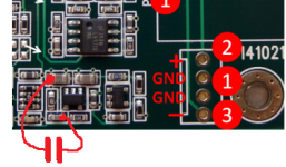
Okay, here is the official recommendation for vref buffer circuit, after I spend some time simulating and real hardware testing. The original circuit was ok, I didn't spend that much time on it originally as things seems to work fine. But yes, there is room for improvements there...
The output capacitors, marked with red, can be paralleled as much as wanted, but a single 47uF X5R 0603 capacitor is really enough and will fit nicely.
The output series resistors need to be much lower, I recommend to parallel the existing one, marked with blue, with a 0.1 ohm 0603 resistor.
The feedback need to be moved to before the output resistor, by paralleling the feedback capacitor, marked with orange, with a low ohm resistors, t.ex. 0.1 ohm 0603.
I strongly recommend to parallel additional parts instead of removing parts as there then is much less chance of damaging anything.
These modification will result in less than 1 mV p-p ripple, at all frequencies, with no peaking or changes in voltage precision. It's also what the next production series will look like.
Attachments
Last edited:
You can use back-to-back, but I don't see real need for this (back-to-back is for 2H HD cancelling, in audio signals).Or 2 polar caps back to back to make a bipolar?
I took the picture from the Soekris website, I didn't notice any difference.
The "feedback" cap and the 10R res are inverted in your photo.
The Soekris PCB photo showing factory upgrades is equal to mine PCB, but not the upgrade; my upgrade change the buffer behavior.
Ironically, my upgrade also results in very low noise and zero peaking in 4V line, so I will make other channel with Soekris propositions to compare.
Last edited:
Would be bridging those resistors an option? Or do we need those little 0.1 ohm resistances?
You need to have those small series resistors on the output, otherwise you will get a peak on the output with those large capacitors.
You can use shorts for the feedback capacitor, but since you already would have to source those 0.1 ohm 0603 resistors it's easier to use those as shorts....
I think 0805 is the correct size.... 47uF X5R 0603 capacitor...
The feedback need to be moved to before the output resistor, by paralleling the feedback capacitor, marked with orange, with a low ohm resistors, t.ex. 0.1 ohm 0603.
If I traced the PCB correctely this will short out and In- (red on the back or inner layer).
Not exactely what I would understand by "feedback to be moved to before the output resistor".
????

I think 0805 is the correct size.
Typing error, the capacitor is off course 47u X5R 6V3 0805.
If I traced the PCB correctely this will short out and In- (red on the back or inner layer).
Not exactely what I would understand by "feedback to be moved to before the output resistor".
????
100% feedback is still feedback 🙂 Also called unity gain buffer....
With this illustration I see I make an AC buffer with my coupling cap, and that will not have the 0R1 proposed by Soekris so maybe it have some peaking. Is more easy and correct in principle using the Soekris proposition, but even so I will compare the 2 alternatives.If I traced the PCB correctely this will short out and In- (red on the back or inner layer).
Not exactely what I would understand by "feedback to be moved to before the output resistor".
????
View attachment 494068
I also have measured all power supplies in DAM and:
For the rest of the power supplies, the 3V3 has sufficiently low noise for applications for which it is, and it confirms what alecm realized: bypass in 3V3 line does not improve things ...
The oscillator module have very low noise in their power pins is not must need upgrade (is well decoupled).
The 1V2 supply has very low noise for a switching power supply, even if Buck supplies tend to have low noise when well designed, as in the DAM. The FPGA itself could generate some noise in the 1V2 supply but is well decoupled and little noise is measured.
Really the only point to receive real upgrade is th 4V supply. Good news to those who do not want to fill the entire plate with capacitors ... and save them for 4V lines.
The grounding in DAM PCB is good and for most measurements and you can put the scope ground at output GND and measure almost same noise than grounding next to target.
The output noise floor is spectacular but if you connect an serial port the SNR degrades by at least 20dB.
Soekris did a great job in supplies for the digital circuits, in my opinion.
Soekris did a great job in supplies for the digital circuits, in my opinion.
Not surprising, this is what he does for a living with his fantastic networking hardware.
hello zfe,If using the second lader for stable Vref load, you need an other sort of inversion than for ballanced mono. Loosely speaking the second ladder needs to play "something" high volume when the "listening-ladder" plays low and vice versa.
More precisely, the bits of the second signal should have all but the sign bit flipped (0->1, 1->0).
I guess that your idea is similar to kinda deglitch method for r2r, in which it utilizes a second dac chip to follow the output of the main dac. However the concrete implemtation was not given in the patent that I read…but in your idea, the switches in both dacs have to switch in the opposite direction. That perhaps means that the glitch Impulses can be neutralized? If yes, I d say it will be a much better way than using high order LPF to deglitch. The Dcs used like 10th order LPF in their early works to deglitch, and that really shocked me…
so,did anybody heard this? TotalDac was mention here,did anybody build dac with this chip in a way that its anywhere close to massively popular 10k french dac?
another question,can this be build to support current mode output,like Bakoon SATRI link or Audio GD ACSS or Krell CAST? if it can have current output I can effectively turn the Bakoon amp from two stage to single stage,becose I dont need the voltage to current conversion stage and as I know simpler means pure sound
another question,can this be build to support current mode output,like Bakoon SATRI link or Audio GD ACSS or Krell CAST? if it can have current output I can effectively turn the Bakoon amp from two stage to single stage,becose I dont need the voltage to current conversion stage and as I know simpler means pure sound
Last edited:
- Home
- Vendor's Bazaar
- Reference DAC Module - Discrete R-2R Sign Magnitude 24 bit 384 KHz