Hi, I'm new on this thread. Does anyone have a complete BOM, scheme and PCB layout (I/V and power supply) for a Buffalo IIISE output stage.
Julien
Julien
Not yet. I dont have Iout DAC. My DAC ESS9023.
Didiet
The Zen I/V is of course designed for current output DACs. I wonder, how many current output DACs are in use today? If one would like to upgrade a CD/DVD/BR-player or even a DAC, does not these often have voltage output DACs, with built-in op-amps?
If you would like to roll your own, you have maybe the Buffalo DAC or the QNKTC DAC. Then there is use for something like the Zen I/V.
/RK
The Zen I/V is of course designed for current output DACs. I wonder, how many current output DACs are in use today?
The best DAC chips from T.I. (Former Burr-Brown), Analog Devices, and ESS Tech feature current outputs. Namely, the PCM179x series, the AD1853 and AD1955, and (I believe) the Sabre32 Reference DACs. In addition, the 24-bit PCM1704 is a current output device. There are as many 'top model' DAC chips featuring current outputs as such DACs featuring voltage outputs. The main vendors offering 'top model' voltage output DAC chips are, Cirrus, Wolfson, and AKM.
Yes, ESS Sabre can work on v or I output. I'll choose current output with the zen I/V, but does anyone have a complete BOM, scheme and PCB layout (I/V and power supply) for a Buffalo IIISE output stage ?
Julien
Julien
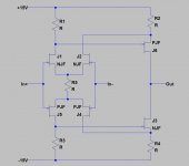
Consider e.g. Texas Instruments DSD1794 (attached). This can accept DSD and flavours of PCM up to 192 kHz. Figures 33 and 34 shows analogue filters for PCM, while figure 35 shows an analogue filter application for DSD. The I/V part can of course be realized with the Zen I/V, while the output could be realized with a simple JFET based opamp, se picture.
However, for DSD, it is recommended a low cut of frequency, while for PCM a much higher is recommended.
This means that most likely, the same analogue stage is not optimum for both DSD and PCM. 🙄
/RK
However, for DSD, it is recommended a low cut of frequency, while for PCM a much higher is recommended.
This means that most likely, the same analogue stage is not optimum for both DSD and PCM. 🙄
/RK
Attachments
Consider e.g. Texas Instruments DSD1794 (attached). This can accept DSD and flavours of PCM up to 192 kHz. Figures 33 and 34 shows analogue filters for PCM, while figure 35 shows an analogue filter application for DSD. The I/V part can of course be realized with the Zen I/V...
A complication arises when utilizing a current output DAC which does not feature an internal output bias offset correcting current-source. These DACs, such as the PCM179x series, ad the AD1955, will either sink or source a D.C. bias current from their output pins. This current must be accounted for by the I/V stage in terms of it's affect on THD, and on eventual D.C. output voltage offset. For example, the DSD1794 needs to source 6.2mA of D.C. bias current in to the I/V circuit in addition the 3.9mA peak signal current. This is a 10.1mA maximum sum, which could easily produce significant amounts of distortion in a relatively low bias zero-feedback circuit, such as the JFET based Zen I/V. As a very general rule-of-thumb, open-loop grounded gate/base type I/V circuits seem to perform best with a quiescent bias current roughly 10 times the peak signal current.
Last edited:
zen i/v with IRFP610 IRFP9610 possible? for TDA1541
second question, possible to use the zen I/V as the input stage of a F5 amp?
second question, possible to use the zen I/V as the input stage of a F5 amp?
You still have the J212 and J175 available. Maybe less performance. Not bad pricing either. Have a look at e.g. Digikey.
As i,m not familiar enough with electronics a question.
I want to try the I/V with my dvd player but the current of the PCM-1792 is to high according to older posts. Its 6,5 ma. Can i use a resistor to lower it ?
If so what wil be a good value ?
I want to try the I/V with my dvd player but the current of the PCM-1792 is to high according to older posts. Its 6,5 ma. Can i use a resistor to lower it ?
If so what wil be a good value ?
No you don't need a resistor on the output but you can change the load resistor on the transistor if the level is too high.
Thanks Wayne, is the bias of 10 ma of the jfets no problem compared to the relatively high output of 6.5 ma of the dac ?
Last edited:
I decided to build a version of ZEN IV of Nelson Pass in January, but I had not yet bought the LSK-LSJ of Linear. I decided to use lateral MOSFETs: 2SK216 and 2SJ77, with an additional circuit in order to polarize the MOSFETs gates with the correct operation (a resistive divider well decoupled and low impedance). It worked well. Very good, by the way! The circuit was applied to a DAC of EAD, the DSP-1000 series III. The original of the same circuit used high-speed AD OpAmps. The result? I donated the original OpAmps for a friend, because the ZEN IV was outrageously higher sonically to the original circuit, about to dethrone my other DAC with CS8416-DF1704-PCM1704, nanocrystalline toroidal transformer for the I / V and output stage Aikido with E88CC Siemens, gold pins!
The DAC of the EAD, for information, use CS8412 receiver, PMD100 digital filter and PCM63 D/A. Yes, I measured them (low level sine) and this passes more than 16 bits, thanks to PMD100 (dithered to 20 bits for PCM63).
The DAC of the EAD, for information, use CS8412 receiver, PMD100 digital filter and PCM63 D/A. Yes, I measured them (low level sine) and this passes more than 16 bits, thanks to PMD100 (dithered to 20 bits for PCM63).
AD1862
Hi everys,
have anyone used this circuit with AD1862 (+-1mA, 2K output impedance)?
what output voltage you get from it? or how much gain you get from this circuit?
thanks in advance
Hi everys,
have anyone used this circuit with AD1862 (+-1mA, 2K output impedance)?
what output voltage you get from it? or how much gain you get from this circuit?
thanks in advance
The gain of this circuit is determined by the drain resistors "more or less" times the current sourced by DAC. You can use a higher supply voltage, which will enable the use of a larger value of drain resistors (to keep the drain voltage to 15V), obtaining an increased gain.Hi everys,
have anyone used this circuit with AD1862 (+-1mA, 2K output impedance)?
what output voltage you get from it? or how much gain you get from this circuit?
thanks in advance
Compared to the PCM63, which has +/-2mA output (approx. 1Vp or 0.7Vrms), you will get half the output voltage using the AD1862 (in my case, using lateral MOSFETs, I got an output value slightly smaller than a conventional DAC, a bit less than the 0,7Vrms, but the my amplifier has plenty of gain and the sound quality compensates completely). So you can use +/-45V to obtain 2k into drain resistors and double gain to compensate the AD1862, for example.
Thank you so much for a proper answer.
it is about a Teac player with 2 AD1862 per channel. between the chips and xlr's you will count 8 opamps per channel! wich is damaged now and I must do something for the babe now. this ZEN i/v seems the right one. hope I can make it works again.
it is about a Teac player with 2 AD1862 per channel. between the chips and xlr's you will count 8 opamps per channel! wich is damaged now and I must do something for the babe now. this ZEN i/v seems the right one. hope I can make it works again.
- Home
- Amplifiers
- Pass Labs
- Zen I/V Converter