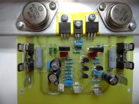
Hi, the first test of the amplifier was quite good. The sound is linear, powerful bass and clear heights. Nothing special to notice. I used only components from the shelf as 2SC5200/2SA1943 and not transistors for higher voltage.
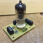
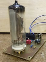
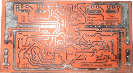
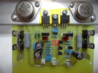
Test module for the tube was soldered only and not tried. It's only a photo to show here. Not enough time 😉
Better would be a ring of solder pads around the tube. They would give more options for measuring and other components...
I found a old Tube-VU. For each channel it can give a nice looking amplifier at the end.
regards Olaf
Attachments
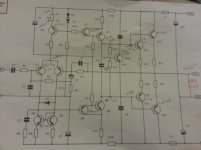
Junction between R12 and R13 should be ground?
Darlingtons are notorious for difficult quiescent current setting. Need to have an adjustable bias, and often higher emitter resistors than usual (1 ohm?). I suspect that the bias was too high, and as the Darlingtons also have poor second breakdown characteristics (derating from 35V) that they may have smoked if the quiescent current was too high.
The MJE340 /MJE350 never have an fT specified. I'd use higher frequency drivers - the stabilisation scheme is generally one I concur with but with slow VAS it might not work.
John.
No Ground between R12 and R13, these are 100K. I lost two output transistors now they are DC. dead short across BE on the TIP146. Im not sure I want to change the transistors at this stage except maybe the outputs, mostly as I don't have any replacements at this stage. Having said that, maybe I get some more suitable outputs for 45V rails. Are the BDW83D and BDW84D readily available? I might ask in the swapmeet.
Do you have any suggestions for the VAS and drivers?
Have you connected input ground to your main (star) ground point? This design requires the input to be configured like this for correct operation.
Hi James, I did not, I just checked it and its not grounded on the PCB. Strange, I have never seen this before. Is it possible that has caused the thing to go into meltdown?
Hello, can some one please confirm that the foil I have and schematic for the D14 darlington version of this amp is correct? I don't want to start buying parts for something that wont work. Thanks.
Attachments
Hi James, I did not, I just checked it and its not grounded on the PCB. Strange, I have never seen this before. Is it possible that has caused the thing to go into meltdown?
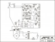
Hope connection diagram will help you. NX-14, AX-14, D-14 etc are connected same way.
I have made this amp for subwoofer duty.
Regards,
Sonal
Attachments
d14 is a working amplifier, there are some diferences between schematic and pcb's layout but enter way you populate it,it should work. i will check later on our local forum about that changes and let you know.

Excellent, thanks all for your help, I may get a new set of outputs and use the resistors, instead of fuses as suggested. Anyone got any suggestions on what I should use for the darlingtons, the ones speced here or are there better ones? I never used darlingtons before. For one thing I need better voltage tolerance than what I have for 45V rails. The BDW83D and BDW84D 120Vceo are better suited to what I have any way.
Excellent, thanks all for your help, I may get a new set of outputs and use the resistors, instead of fuses as suggested. Anyone got any suggestions on what I should use for the darlingtons, the ones speced here or are there better ones? I never used darlingtons before. For one thing I need better voltage tolerance than what I have for 45V rails. The BDW83D and BDW84D 120Vceo are better suited to what I have any way.
Use resistors to check amp, if it's working properly replace them back with fuse.
10-22 ohm resistor will do the job.
Thanx for your quick reply.
I'm interested with SR150, but unable to fetch schematic and pcb layout in pdf. could you please share if you have it.
hello.I suggest you to use 2sc 3856/2sa 1492 5pair which is available in kolkata chndni market. And use Rod Elliot subwoofer amplifier circuit with 40 0 40v 6 amp transformer.It will give you punching bass...
hello.I suggest you to use 2sc 3856/2sa 1492 5pair which is available in kolkata chndni market. And use Rod Elliot subwoofer amplifier circuit with 40 0 40v 6 amp transformer.It will give you punching bass...
Thanks for your suggestion Pallab.
I know 2SC3856 & 2SA1492 are available in Kolkata @Rs.180/pair, but as i mentioned in my post that i already have 4 pairs of 2SC5200 & 2SA1943 and want to make use of it. Anyway thanks for your suggestion for "Rod Elliot subwoofer amplifier" I'll also try this after SR-150. I love to make amplifiers.🙂🙂🙂
Further suggestions will be appreciated.
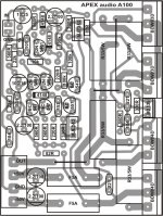
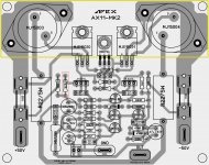
AX11 - TO3 Version
Can anyone help me with this. The 47R resistor outlined in Red Burns up Instantly upon power up. I am using +- 44V rails with 10R/5W resistors in each rail and .5a fuses. I have checked all of the other Transistors & all Test OK.
Can anyone help me with this. The 47R resistor outlined in Red Burns up Instantly upon power up. I am using +- 44V rails with 10R/5W resistors in each rail and .5a fuses. I have checked all of the other Transistors & all Test OK.
Attachments
AX11 -TO3
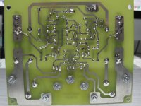
Terry, The MJE350 Tested good, but i replaced it anyway with a new one. Same results. Can't find any Solder bridges. See if you see anything wrong here. I had cut the 2 traces to put the fuses in front of the +-44V that feed those 10R 47R combo. I fixed the cut traces, as the fuse still didn't blow.
Thanks for looking.
Attachments
Hi Rick,
I don't see any solder bridges. However, It looks like you have two more burnt resistors, see attached. I see you have Kapton tape installed but have you done a continuity test between all the the transistors and the heatsink? I sure acts like there is a short somewhere.
I don't see any solder bridges. However, It looks like you have two more burnt resistors, see attached. I see you have Kapton tape installed but have you done a continuity test between all the the transistors and the heatsink? I sure acts like there is a short somewhere.
Attachments
Hi Terry,
Both those 680R resistors were ok.Measured 674R & 679R. I replaced them anyway.
Also i went over the GND again. NOTHING from the Heatsink to ANYTHING. Also went from GND Tab to everything and only those parts that connect to the GND had continuity. This is Really WEIRD! Don't know if anybody else has built this to see if it works. I am WAY out of my element here. Thanks for looking it over & helping out. Think i will just move on to something else for now. I have built the AX11 Standard one & it sings Sweetly. I had hoped this one would be the same but with more Grunt.
Rick G.
Terry, The MJE350 Tested good, but i replaced it anyway with a new one. Same results. Can't find any Solder bridges. See if you see anything wrong here. I had cut the 2 traces to put the fuses in front of the +-44V that feed those 10R 47R combo. I fixed the cut traces, as the fuse still didn't blow.
Thanks for looking.
This likely isn't your issue but it looks like you have 22 ohm(22R) emitter resistors instead of .22 ohm(R22).
- Home
- Amplifiers
- Solid State
- 100W Ultimate Fidelity Amplifier