I've got a schematic half done. I'll start a new thread when it's complete.Hey , Jeff. We could discuss some "gibberish" here ?
I know what you are saying with the uncalibrated hall current sensors now.
the ones with the built in "wire" (specc'ed conductor) are pre - calibrated.
A trace based one would have to be scaled to the users trace thickness/
width.
ACSxxxx says " motor control" for an app. Motors would surely throw off
quite the EMF. Look to the suggested uses to determine whether a humble
DIY amp would exceed what ever industrial uses there are for the IC.
OS
Hi Guys,
Thanks for moving the discussion over to here. I certainly didn't mean to infer it was gibberish. I'm just trying to keep that thread on topic because when I get questions about building all these wonderful boards I always send folks there as there is a lot less information to sift through to get to the answers they need. Off topic discussions make it more difficult. I too built Valery's incredible 21st century protection board. I began building the one that Jeff laid out too but he was redesigning at the time so I stopped. If I ever get around to installing one of the hybrid amps into a case I am going to use that protection board.
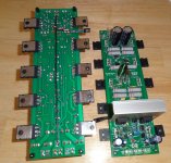
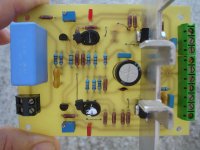
I've got the OPS boards populated now. I just need to clear up some heatsinks and give it a test run. I decided to use a wire under the board to connect the grounds together and will fly the VBE on wires and mount it on top of one of the outputs. We'll see how it goes.
Blessings, Terry
Thanks for moving the discussion over to here. I certainly didn't mean to infer it was gibberish. I'm just trying to keep that thread on topic because when I get questions about building all these wonderful boards I always send folks there as there is a lot less information to sift through to get to the answers they need. Off topic discussions make it more difficult. I too built Valery's incredible 21st century protection board. I began building the one that Jeff laid out too but he was redesigning at the time so I stopped. If I ever get around to installing one of the hybrid amps into a case I am going to use that protection board.
I've got the OPS boards populated now. I just need to clear up some heatsinks and give it a test run. I decided to use a wire under the board to connect the grounds together and will fly the VBE on wires and mount it on top of one of the outputs. We'll see how it goes.
Blessings, Terry
Attachments
Last edited:
I've started a thread here http://www.diyaudio.com/forums/solid-state/276533-solid-state-rail-fuse-replacement.html#post4375114 for the SS rail fuse design.

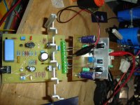
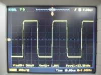
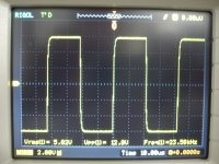
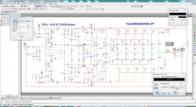
Symetri is singing now!
More details soon.
Very Nice🙂
Looks good, what is your first impressions?
Symetri
Some resistors values must be changed.
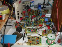
Last picture....the IPS war!
Some resistors values must be changed.
Last picture....the IPS war!
Attachments
Last edited:
Not yet my friend.😱thimios what about sound ? instruments and voice 🙂
Hi Thimios,
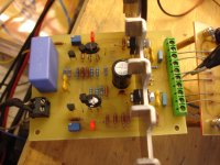
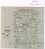
I see you used 47R for all the emitters. Any issues? Looks like R15 is running a little hotter than R16. Are R23 and R30 equal? Ha, I have a pile like that too. Every so often I will spend a day hooking them all up and listening to them.
Blessings, Terry
I see you used 47R for all the emitters. Any issues? Looks like R15 is running a little hotter than R16. Are R23 and R30 equal? Ha, I have a pile like that too. Every so often I will spend a day hooking them all up and listening to them.
Blessings, Terry
ok man take your time and enjoy man that is the most important part of the hobby 🙂
note:
I'm just so happy that this section have so many IPS to chose from and to learn 🙂
from each individual ones this is magnificent !
Regards
Juan
note:
I'm just so happy that this section have so many IPS to chose from and to learn 🙂
from each individual ones this is magnificent !
Regards
Juan
Attachments
Last edited:
Here is as built.Hi Thimios,
I see you used 47R for all the emitters. Any issues? Looks like R15 is running a little hotter than R16. Are R23 and R30 equal? Ha, I have a pile like that too. Every so often I will spend a day hooking them all up and listening to them.
Blessings, Terry
Terry i believe that it is time increasing emitter resistors.Lets wait OS🙂
Attachments
Here is as built.
Terry i believe that it is time increasing emitter resistors.Lets wait OS🙂
When I get up today I will try changing R24,25,28&29 to 47R and see if that will bring down R15 & R16 a little.
When I get up today I will try changing R24,25,28&29 to 47R and see if that will bring down R15 & R16 a little.
The current throught R15,16 are determined by CCS Q5 and Q6🙂
Yes but this affect the VAS current also.The current throught R15,16 are determined by CCS Q5 and Q6🙂
I will increase the emitter resistors(R9,R10,R14,R17) to 68R.
Yes but this affect the VAS current also.
I will increase the emitter resistors(R9,R10,R14,R17) to 68R.
Why do you want to increase emitter resistors?
Are there other things in the circuit you want to change now?
Sorry, I've been lazy today. Let us know how that works out.
Terry,
How many people do you have working with you on this stuff?
I don't think I've ever seen anyone crank out as much stuff from
scratch as you do, and make or proto your own boards to boot.
Do you have your own supply house across the street for parts?
or
Is it out back in the barn?
Kudo's ,

No worries it's freshly brewed sarsaparilla.
Why do you want to increase emitter resistors?
Are there other things in the circuit you want to change now?
My thinking, let me know if I'm off base here, was that lowering the value of the VAS emitters would require less current from the front end. The front end is supposed to be about 3.8mA when the VAS is at 11mA. With the emitters all the same, the front end is running >=4.2mA.
Do you have your own supply house across the street for parts?
or
Is it out back in the barn?
I keep most all of the 1/4w resistor values in stock as well as many of the most commonly used caps. I usually buy lots of 100 when ordering transistors. They are cheaper that way and it gives me better matches. My least favorite thing is to have to pay shipping and then wait for several days for just a couple parts to arrive.
Blessings, Terry
Possibly lowering R23,R30 to something 56R-68R maybe the best practice.But where is Pete?Here is as built.
Terry i believe that it is time increasing emitter resistors.Lets wait OS🙂
- Home
- Amplifiers
- Solid State
- Slewmaster - CFA vs. VFA "Rumble"