So how's the temperature of the AD845s now? I remembered after posting this mod that you'd not decreased their supply yet so they must be getting quite toasty with the extra 8mA or so of bias?
FWIW, I found my IR temperature gun! After well over 12 hours of continuous playing, the top of the AD845 package was about 115 degrees F which is about 46 degrees C. Looks like the max operating temp for the AD845 is 70 degrees C, so I'd say I'm safe.
This is in the open air, since this will no longer fit in the stock case.
The 70 degree C figure is for ambient temperature, not the package temperature which can go quite a bit higher than ambient. Looks like you're safer than you thought. If you box it up though the ambient temperature might go higher than 46oC.
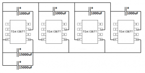
I’m still very much enjoying this project, though I sometimes think I’m in over my head. Did a lot of reading and finally ordered the 4x TDA1387 as well as two 1uf 550v Panasonic to replace the end caps, four 1000 uF 10v Nichicons to add capacitance across pins 7 to 4 and two 15000uF 6.3V Panasonics to add capacitance across pin 4 and 5. Unfortunately I’ve to wait quite some time for these parts to arrive. This gives me time to do some more reading, not a bad thing.
Is the schematic I made the correct implementation of the modifications?
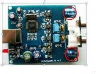
I don’t understand what you mean with the I/V resistor. I thought this is the opamp used to convert the current from the DAC chip into an analogue voltage. It seems to me the 4x TDA1387 doesn’t have one. Are the capacitors with the red circle the coupling capacitors?
What will happen if I just connect this DAC with an RCA cable to the input of my SSMH amp?
Is the schematic I made the correct implementation of the modifications?
You're welcome 🙂
The output voltage directly from the TDA1387 chip is limited to 3.5V peak (for a 5V supply). But that's over 1VRMS so will be in the same ballpark as an iPod output. So I'd say yes you can certainly drive this valve amp from a 4*TDA1387 DAC. The I/V resistor should be 820R to 0V and you'll need to ensure you have a coupling cap between the positive side of that resistor and your output.
I don’t understand what you mean with the I/V resistor. I thought this is the opamp used to convert the current from the DAC chip into an analogue voltage. It seems to me the 4x TDA1387 doesn’t have one. Are the capacitors with the red circle the coupling capacitors?
What will happen if I just connect this DAC with an RCA cable to the input of my SSMH amp?
Attachments
Your schematic looks good to go for the mods, yep 🙂
Your *4 DAC doesn't have any opamps, its using passive I/V. I suspect (but can't see clearly from the picture) that your I/V resistors are between the two capacitors near the RCA outs (a rectangular blue one and a yellow bead). Yes you've correctly identified the coupling caps.
I don't know what an 'SSMH amp' is, sorry. I think the answer will be 'you'll hear music' but of course you'd need to connect a USB source to it.
I don’t understand what you mean with the I/V resistor. I thought this is the opamp used to convert the current from the DAC chip into an analogue voltage. It seems to me the 4x TDA1387 doesn’t have one. Are the capacitors with the red circle the coupling capacitors?
What will happen if I just connect this DAC with an RCA cable to the input of my SSMH amp?
Just to be clear, two fairly different DACs have been discussed in this thread. The bulk of the posts (and the original subject) was not about the 4x DAC you pictured, but instead about a DAC with 8x tda1387 chips. I'm not trying to be the thread topic police, just trying to make it clear that you have to be careful about the context, i.e. are we talking about the 4x or the 8x.
So, indeed, the 4x DAC you're talking about does not have opamps. (That's a feature of the main topic of this thread, the 8x DAC.)
The caps you circled are the coupling caps, and I believe their purpose is for blocking DC (from preventing it from entering your amp). All the amps I've been working with have their own DC blocking capacitors, so technically I don't need them on my DAC. But I'm not sure about your amp, you'd have to check. Generally you don't want DC going into your amp, and if it reaches your speakers, it can damage them (presumably it can damage some amps too).
I think your schematic looks right, but I suggest waiting on Abrax's confirmation! Take a look at post #137 on page 14 of this thread. I added capacitance across pin7 on my x4 DAC, you can see my pictures. The stock capacitors labeled "105" correspond exactly to pin7-pin4 (the stock "105" caps sit "between" the tda1387 ICs). What I did is simply remove the stock ones and use the solder pads to attach my bigger caps.
And I think (going from memory as I don't have the boards in front of me), the "104" capacitors correspond to pin5-pin4. (I know for a fact they do on the x8 DAC.) Space will be tight but you could also follow suit and use one or more of those spots for adding pin5-pin4 capacitance.
You'll also see in my pictures I replaced the stock electrolytic DC-blocking caps with nicer polypropylene film caps. (But as I said above, I know my amps have their own DC blocking caps, so I actually could have simply used jumper wires instead of caps.)
Be careful unsoldering the stock SMT caps, and adding your own big(ger) electrolytics. When I did it, I managed to pull off a couple solder pads, and had to correct with extra wire leads (you can see them in my pictures).
110v is here
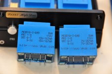
Received some goodies from China tonight: another one of these tda1387 x8 with stock 110v transformers, and two additional 110v transformers. Listening to the stock 110v version as I type this. Not as refined as the modded one, but not offensive. In fact this one sounds better than how I remember the stock 220v sounding. Maybe there's some goodness in avoiding the 110-to-220 external transformer I have for the other one? (Or maybe it's just because I'm forced to keep the volume down with the kids in bed.)
In the pics below are the standalone 110v transformers. Note the 220 version has 7.5V for the digital side, while the 110 version has 7.0V. Doesn't appear to be an issue...
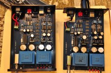
The other pic is the stock 110 on the left, with my modded 220 on the right. New stock version has electrolytic caps for DC-blocking, oh no! 🙂
Nothing but good things to say about seller Doukmall on ebay.
Received some goodies from China tonight: another one of these tda1387 x8 with stock 110v transformers, and two additional 110v transformers. Listening to the stock 110v version as I type this. Not as refined as the modded one, but not offensive. In fact this one sounds better than how I remember the stock 220v sounding. Maybe there's some goodness in avoiding the 110-to-220 external transformer I have for the other one? (Or maybe it's just because I'm forced to keep the volume down with the kids in bed.)
In the pics below are the standalone 110v transformers. Note the 220 version has 7.5V for the digital side, while the 110 version has 7.0V. Doesn't appear to be an issue...
The other pic is the stock 110 on the left, with my modded 220 on the right. New stock version has electrolytic caps for DC-blocking, oh no! 🙂
Nothing but good things to say about seller Doukmall on ebay.
Attachments
Ok, time for another hand-holding request...
I'm reviewing post #24 and #25 on page 3 for the NOS droop filter:
The circuit in post #24 seems quite straightforward. But I don't quite understand the pink lines in your drawing in post #25. Looks like you have a line (in series with the cap+resistor) going to one leg of the yellow capacitor (which you X'ed out). It looks like that leg goes right to ground. But I don't see a ground in your circuit diagram in the previous post.
I think once I get this straightened out, I'll be ready for the next mod(s). What do you suggest? Might as well start preparing.
Thanks again!
I'm reviewing post #24 and #25 on page 3 for the NOS droop filter:
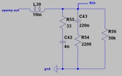
I've been listening now for an hour or so and this filter's definitely for keeps. The rise in HF response makes it sound just a tad more transparent and I'm getting more of an 'in focus' sound, closer to my reference DAC. Here's a hasty sketch of how to connect the filter (pink lines although only one RC network is shown in the sketch). I took out the square blue coupling caps as I already have input caps on my active speakers. If you need to preserve AC coupling move these caps to the output of the LC filter board - the Coilcraft inductors sit (face down) on my board where these caps used to be.
The circuit in post #24 seems quite straightforward. But I don't quite understand the pink lines in your drawing in post #25. Looks like you have a line (in series with the cap+resistor) going to one leg of the yellow capacitor (which you X'ed out). It looks like that leg goes right to ground. But I don't see a ground in your circuit diagram in the previous post.
I think once I get this straightened out, I'll be ready for the next mod(s). What do you suggest? Might as well start preparing.
Thanks again!
The ground is there, just LTSpice turned it through 90degrees (pointing left).
The X'd capacitor is to be removed.
As for the next mod - its fairly complex to install the passive filters as it means all kinds of changes. Here's a brief list - see if you feel up to it:
1) Remove the opamps
2) Build 4 channels of passive filtering
3) Separate the DACs into positive and negative phases (4 DACs for each phase)
4) Include a digital inverter for the negative phase
5) Implement single transistor I/V stages on each group of 4 DACs
6) Build 4 channels of classA buffers (emitter followers + CCSs)
7) Wind ferrite output transformers to do bal-SE conversion
The ground is there, just LTSpice turned it through 90degrees (pointing left).
Ahh, that's the triangle, right? Guess I expected ground to be three parallel lines in decreasing length, but a quick Google shows different types of ground have different symbols. 😱
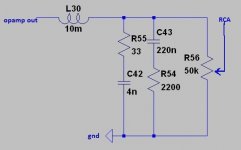
Is the attached pic correct then? (I understand that 50k resistor is optional, for volume control.)
As for the next mod - its fairly complex to install the passive filters as it means all kinds of changes. Here's a brief list - see if you feel up to it:
1) Remove the opamps
2) Build 4 channels of passive filtering
3) Separate the DACs into positive and negative phases (4 DACs for each phase)
4) Include a digital inverter for the negative phase
5) Implement single transistor I/V stages on each group of 4 DACs
6) Build 4 channels of classA buffers (emitter followers + CCSs)
7) Wind ferrite output transformers to do bal-SE conversion
I'm up for anything, given adequate assistance. 🙂
Some high-level questions before I go down this road:
- Regarding items (3) and (4) - I'm guessing this involves some (serious?) "surgery" on the PCB, as the eight DAC chips will no longer be in parallel, but two independent groups. What's involved in a digital inverter? Is there an off the shelf IC that does that, or do you create such a circuit yourself?
- Edit: at what level are you doing the digital inversion, SPDIF or I2S? At some point I want to use my Amanero with this, which outputs I2S, and is what the tda1387 takes as input.
- Is step (7) optional if the end goal is balanced output? My amps all support balanced input...
- Any pics of all this? 🙂
Attachments
Last edited:
Is the attached pic correct then? (I understand that 50k resistor is optional, for volume control.)
Yep - the 50k is part of the next box in the chain, not required in the DAC.
I'm up for anything, given adequate assistance. 🙂
Great attitude!
Regarding items (3) and (4) - I'm guessing this involves some (serious?) "surgery" on the PCB, as the eight DAC chips will no longer be in parallel, but two independent groups.
Fairly serious but in practice it just means there are two data feeds (meaning you break the pin3 trace into two parts).
What's involved in a digital inverter? Is there an off the shelf IC that does that, or do you create such a circuit yourself?
You have the choice of various off the shelf ICs which do this job. I used a 74HC04 (I think) which contains 6 such inverters, only one is needed. Or you can save on wiring by going for an individually packaged inverter (normally a 5pin SOT style package).
at what level are you doing the digital inversion, SPDIF or I2S?
Digital inversion has no effect on S/PDIF, so I2S yes. It applies only to the D (data) wire.
At some point I want to use my Amanero with this, which outputs I2S, and is what the tda1387 takes as input.
Can't forsee any problem with that - you'll bypass the S/PDIF receiver.
step (7) optional if the end goal is balanced output? My amps all support balanced input...
Yes optional if you want balanced output. You'll need caps instead as the discrete buffers have an offset around 0.6V.
Thanks for the nudge about getting some pics up......😎
If I did want to include the volume control... I updated the schematic with the 50k resistor changed to a potentiometer diagram. Just want to make sure I understand it correctly.
-Matt (who needs to learn to use a real circuit drawing program instead of MS Paint)
-Matt (who needs to learn to use a real circuit drawing program instead of MS Paint)
Attachments
One more question before I go to bed: with regards to splitting the DACs into two groups of four: this means the first group will basically be no different than the stock 8x DACs, and will output L+ and R+.
The other group of four will be the same, except the I2S data line is inverted. So the output of this group is L- and R-.
Is that right?
I assume the inverter circuit adds some delay. Maybe that delay is tiny enough to not matter, i.e. negligible? Or does the non-inverted signal need a similar kind of added (artificial) delay to match the delay added by the inverter?
If you did want to include a volume control it wouldn't be a great idea to do it that way inside the DAC. For the reason that the output impedance via the pot is too high to bear much cable capacitance without HF droop happening. Its fine to do it that way inside a preamp though, but I'd include a capacitor to prevent DC on the pot.
In regards to your bedtime question, I assume you meant 'no different than the stock 4x DACs' ? In which case yes, correct.
The inverter does add some delay that's right - its not enough to reach to the time displacement of two adjacent clock edges (which is around 300-400nS) where it could cause damage to the 1387's operation. If you're concerned about the delay you could use two gates from a 74HC86 - one to invert and the second to buffer.
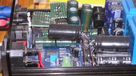
Here's a picture of the first generation mods (opamps still extant) applied to my first DAC. The small green perfboard pieces are doing the LC filtering (that's the one to the left) and the smaller of the two boards has two current sources on it which counteract the offset current out of the DAC chips.
Attachments
I'm around!
did you figured it out Matt?
No link to case at all, just brought RCA's ground back to supply and no more after opamp's filter one.
As for mine, right now I plan a cheap and good AD845 output, with the filter given by Richard on post 24. It’s 16/44 dedicated, my very use, but if I do send higher res files -say 24/96-, what will happen? Or I built a second filter and switch on the one I need… I have all parts but the coils which are sold on uk.fleaBay. I’ll also remove half DACs if it’s still better than 8 ones stressing the opamps, isn't it?
But I have questions for you gents:
Is the 750R the feedback resistor for opamp? How to calculate or its value the best for the AD845?
The whole case is very hot, I guess the supply parts with heatsinks generate most of the heat, even if I’ve read that the AD845 runs also very hot, any things on the supply I can change to lower the heat with no loss on SQ? I already plan to drill few holes under the chassis to let it breath under as it’s almost a closed box under with the pcb sealing it. 10/12V opamp rails and 200/300R feed resistors?
thanks fellows!
Matthieu
did you figured it out Matt?
No link to case at all, just brought RCA's ground back to supply and no more after opamp's filter one.
Hi Malefoda, if you're still following this thread, this is from post #53, back on page 6:
Is that black wire on the bottom of the board for what Abraxalito mentioned back in post #6 on page 1:
And on the topside of the board, it looks like you cut that big trace between the blue and yellow caps, right?
Rather than cutting the trace, would it make any more sense to cut the RCA ground lead, and directly connect that to the transformer ground? Can that be run to chassis ground? Or the the earth pin of the mains?
Also, what are those little SMT capacitors on either side of the black wire on the bottom of the board?
As for mine, right now I plan a cheap and good AD845 output, with the filter given by Richard on post 24. It’s 16/44 dedicated, my very use, but if I do send higher res files -say 24/96-, what will happen? Or I built a second filter and switch on the one I need… I have all parts but the coils which are sold on uk.fleaBay. I’ll also remove half DACs if it’s still better than 8 ones stressing the opamps, isn't it?
But I have questions for you gents:
Is the 750R the feedback resistor for opamp? How to calculate or its value the best for the AD845?
The whole case is very hot, I guess the supply parts with heatsinks generate most of the heat, even if I’ve read that the AD845 runs also very hot, any things on the supply I can change to lower the heat with no loss on SQ? I already plan to drill few holes under the chassis to let it breath under as it’s almost a closed box under with the pcb sealing it. 10/12V opamp rails and 200/300R feed resistors?
thanks fellows!
Matthieu
Is the 750R the feedback resistor for opamp? How to calculate or its value the best for the AD845?
The value is calculated based on the output voltage swing you want for maximum digital level. Normally for a CD player or DAC this is 2VRMS, meaning 5.6V peak-peak. Since each DAC outputs 1mA peak-peak the I/V resistor should be 5.6/0.008 which I calculate as 700 ohms. Looks like they chose the next highest value above that.
The whole case is very hot, I guess the supply parts with heatsinks generate most of the heat, even if I’ve read that the AD845 runs also very hot, any things on the supply I can change to lower the heat with no loss on SQ?
I think I talked a bit about this earlier in the thread. The regulators are shunts and they're fed by largeish resistors. The resistor's values can certainly be reduced which will probably if anything slightly improve the SQ rather than degrade it. Reducing the opamp rails can reduce the heat even further.
A mod I just thought of is to replace the resistors with LM317s configured as current sources. I might well try this and see if there's any difference. According to my calculations it should improve the ripple rejection of the PSU, particularly at lower freqs but I don't know if its a issue for SQ at present.
Hi Richard,
I'm confused as in post 25 you advise :
Thanks
I'm confused as in post 25 you advise :
and now lower them 😉 I'm lost! I think I mix things amd need help in that matter.The resistors ringed in [...] green marks indicate the resistors feeding the shunts which are to be increased - add a 1W 100R in series with those already there by standing the existing Rs up vertically and placing the new Rs alongside.
Thanks
Ah yeah my mistake when I said 'reduced' I dunno what I was thinking, probably my brain was racing ahead thinking about the voltage rails being reduced. I meant to say 'the resistors can certainly be increased' - thanks for pointing that faux-pas out 🙂
It's outside heat damaging our brains! But no resistors outside to turn the sun off 🙁
Thanks Richard!
Thanks Richard!
Must be the inside heat here (within my brain) doing the damage coz outside its only 18oC - July's normally about twice that figure here. Something strange is happening to our weather.
- Home
- Source & Line
- Digital Line Level
- TDA1387 x8 DAC: let's check its design, mod it -or not-, play music -or not! :(-