If you have 1.8V of DC then the blocker is probably not going to block all of it. You need to add another bridge rectifier to the blocker.
I'm just guessing here but a good blocker with large caps and high current bridge should do the job.If you have 1.8V of DC then the blocker is probably not going to block all of it. You need to add another bridge rectifier to the blocker.
I'm just guessing here but a good blocker with large caps and high current bridge should do the job.
Stop guessing 😉
I don't know what you have done wrong.
But if you have explained the circuit change correctly, then I must agree with Nigel.
Either impossible, or imagination, or some new physics.
But if you have explained the circuit change correctly, then I must agree with Nigel.
Either impossible, or imagination, or some new physics.
Stop guessing 😉
With 45 years in the game, for me, a guess is as good as an assurity.
I think it is possible to have bass attrition if the caps are not big enough. I use 4700uf 50V high ripple caps and 35A bridge. If the caps are small he may be getting a voltage drop when power is needed on bass note. Also I build power filters into my blockers.
But, yes you guessed it, I'm just guessing here. Take that as an assurity.
But, yes you guessed it, I'm just guessing here. Take that as an assurity.
The capacitors pass the AC of the mains frequency.
The capacitors MUST be sized to pass that AC with minimal voltage drop.
The diodes do nothing for the DC blocking capability.
The diodes are there to pass start up current, or fault current, if either exceeds the current passing capability of the capacitors. If this happens the diodes prevent the capacitors operating as DC blockers.
Design the capacitors to pass your normal current range. The primary current into a ClassAB amplifier's transformer is quite peaky. The caps MUST BE DESIGNED to pass this peaky current during "normal" operation.
One can use single inverse parallel diodes as the fault/startup current bypass. This limits the "normal" voltage drop across the DC blocking capacitors to <500mVpk.
That decision to use single diodes results in very large capacitance.
Using two or three diodes in series and then doing inverse parallel, allows the volts drops across the DC blocking capacitors to be increased to 1000mVpk or 1500mVpk.
That results in half or one third of the required very large capacitance.
Here's my example calculation.
dual inverse parallel diodes giving 1000mVpk as the volts drop across the capacitors.
inverse parallel capacitors with each half consisting of back to back polar electrolytics.
four off 4m7F in inverse parallel and back to back series connection gives an effective capacitance of 4m7F
For a 50Hz supply
Xc = 1/2PiCF = 1/2/3.14/0.0047/50 = 0.68ohms
For a sinewave with a peak value of 1000mV the peak current will be 1V/0.68 = 1.48Apk
The rms value for a continuous sinewave would be 1.04Aac
But we know that the primary current follows roughly the secondary charging pulses where the peak current is anywhere between 2times the rms to 10times the rms current.
Lets just assume near the lowest value and use 3times.
i.e. for a peak value of 1.48A the equivalent rms current would be around half an ampere.
the average power of a 230Vac transformer passing an average rms primary current of half an ampere is 115VA.
If you have a 230VA transformer running quite hard then you would need 8capacitors for an effective 9m4F
For a 345VA running quite hard, or a 500VA running more gently, or a 1000VA running very gently, I would use three sets of capacitors resulting in 14m1F (12off 4m7F caps) for a current capability of ~4.5Apk with a maximum voltage drop of around 1000mVpk
I use exactly that for each of my 600VA transformers.
BTW, I use 1n5404 as the 4 diodes in series inverse parallel.
Last edited:
I once gave Alex a sugar pill and told him it was 3x hits of acid. He ran off, freaking out, about an hour later. I lost contact with him and then he resurfaced on here years later, and now says he lives in Boise ID.
So you tell me, does he hear what he hears?
So you tell me, does he hear what he hears?
I tried it with some type of Felix and all returned to be correct. DC Blocked alone make sound thin and bright. Please see pictures of what I used. My SS rectifier is generic one with 25A 600V.
Attachments
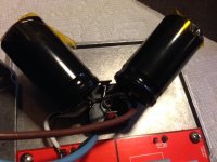
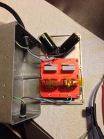

I tried it with some type of Felix and all returned to be correct. DC Blocked alone make sound thin and bright. Please see pictures of what I used. My SS rectifier is generic one with 25A 600V.
My general suspicious were correct. There's no error here, other than inexperience with power conditioning.
I've wondered how much a DC blocker could affect sound, I always thought it was clear, but everyone has sweared they cannot.
Same sound via both ways: reverse when DC Blocker is first and back when Felix is first and then DC Blocker.
Just with DC Blocker, the sound is thin with limited low and mid low.
Just with DC Blocker, the sound is thin with limited low and mid low.
You still need to add more rectifier bridges, until you get 1.8VDC on the capacitors if it's the amount on the line. 1.8VDC means you're listening to rectifier noise, because one is not enough to make the the DC go to the capacitors. The Felix reduces this noise.
Once you do that, it should sound really nice with a filter and zero switching noise.
Once you do that, it should sound really nice with a filter and zero switching noise.
Can you send me a drawing how to connect 2 rectifier bridges together. You will simplify my work.
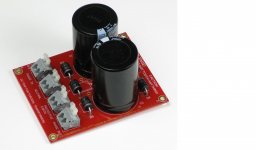
I used these attached 2 pieces on my F5T monoblocks (they are removed mechanical audible noise from my 1000VA toroids). I also used one on my Salas Phono Raw DC box. It also has quite big toroid (200VA).
It has 3 diodes forward and 3 backwards.
I used these attached 2 pieces on my F5T monoblocks (they are removed mechanical audible noise from my 1000VA toroids). I also used one on my Salas Phono Raw DC box. It also has quite big toroid (200VA).
It has 3 diodes forward and 3 backwards.
Attachments
I tried it with some type of Felix and all returned to be correct. DC Blocked alone make sound thin and bright. Please see pictures of what I used. My SS rectifier is generic one with 25A 600V.
My general suspicious were correct. There's no error here, other than inexperience with power conditioning.
I've wondered how much a DC blocker could affect sound, I always thought it was clear, but everyone has sweared they cannot.
Same sound via both ways: reverse when DC Blocker is first and back when Felix is first and then DC Blocker.
Just with DC Blocker, the sound is thin with limited low and mid low.
If the capacitors are too small then the DC blocker will not operate properly.You still need to add more rectifier bridges, until you get 1.8VDC on the capacitors if it's the amount on the line. 1.8VDC means you're listening to rectifier noise, because one is not enough to make the the DC go to the capacitors. The Felix reduces this noise.
Once you do that, it should sound really nice with a filter and zero switching noise.
You need the capacitors to pass the PEAK Primary current without reaching the diode bypass voltage.
That PEAK Primary current could be as high as 10times the rms current.
My example calculation used a value of 3times rms current.
Lets just assume near the lowest value and use 3times.
i.e. for a peak value of 1.48A the equivalent rms current would be around half an ampere.
half an ampere through a 110/120Vac transformer is an average power @ the transformer of ~60W, but less at the PSU DC voltage. expect ~70% of 60W i.e. the DC power available would be ~40W
Last edited:
So, in other words, if i use it as for example for B1 buffer which is set as hotrod with 600mA Constant Current, then I need about 6A (x10 from CC) ripple current spec for my caps. Right?
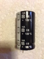
My caps are:
10000uF
25mm x 45mm
(120Hz)3.20A/ (10k-100kHz)3.68A
ESR 0.041/ 0.031
P/N ECOS1VA103CA
My haedphope amp is set to 360mA CC.
So, these caps should work just fine.
Anyway, I'll try to use other type/brand with tougher current spec. Lets see...
My caps are:
10000uF
25mm x 45mm
(120Hz)3.20A/ (10k-100kHz)3.68A
ESR 0.041/ 0.031
P/N ECOS1VA103CA
My haedphope amp is set to 360mA CC.
So, these caps should work just fine.
Anyway, I'll try to use other type/brand with tougher current spec. Lets see...
Last edited:
I think it is possible to have bass attrition if the caps are not big enough. I use 4700uf 50V high ripple caps and 35A bridge. If the caps are small he may be getting a voltage drop when power is needed on bass note. Also I build power filters into my blockers.
But, yes you guessed it, I'm just guessing here. Take that as an assurity.
If the rail voltages drops you get clipping, you don't get reduced bass. I can see how some people could hear this as brightness.
This is not right thinking, I'm afraid.I think it is possible to have bass attrition if the caps are not big enough. I use 4700uf 50V high ripple caps and 35A bridge. If the caps are small he may be getting a voltage drop when power is needed on bass note. Also I build power filters into my blockers.
But, yes you guessed it, I'm just guessing here. Take that as an assurity.
If the caps are too small the current will go through the diodes instead and the DC removal effect will be less but you won't hear anything special in your speakers.
Alex, so long as the capacitance values are correct;
First measure before the DC trap for DC. Confirm you have 1.8vDC. Now measure it in the middle of the diode bridge where the wire connects the two tabs (from that to neutral).
If you have 1.8vDC before, and 1.8vDC in the bridge, you've got an problem. Your capacitance and/or single diode bridge isn't enough. If you've got lower DC, like 1.2vDC on the bridge point, you're only dropping it .6vDC and you'd want to use probably three diode bridges. (And if it's .8vDC, use two bridges)
Here's the schematic.
Notice that most voltmeters can measure millivolt or a volt if you have 230 VAC at the same time. Th value you will get is not true.
- Home
- Amplifiers
- Power Supplies
- DC blockers and mains filters