I would duplicate the output resistors.
Use the on board resistor to feed the capacitor output (AC coupled).
Add another resistor to feed the DC capable output.
Use the on board resistor to feed the capacitor output (AC coupled).
Add another resistor to feed the DC capable output.
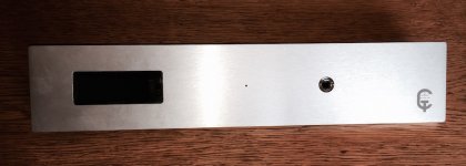
Finally got my faceplate back from the machine shop ... finished pics coming after this weekend's build session ...
Nice avatar logo depiction. Is it laser etched?
Nice avatar logo depiction. Is it laser etched?
Yes ... laser etched 😎
Yes ... laser etched 😎
Do you outsource the Laser etching or do you have your own machine? Curious about acquiring a small machine for projects..
BTW: I've been running Mez for about a month and half with no chassis.. It certainly is reference quality🙂. Driving Marantz MA500 Mono's is special, puts them in a new and better place.. Also connected to 2a3 14 watt mono's is something special..

Do you outsource the Laser etching or do you have your own machine? Curious about acquiring a small machine for projects..
I have a local shop that does all my machining and laser work.
Pass DIY Addict
Joined 2000
Paid Member
BTW: I've been running Mez for about a month and half with no chassis.. It certainly is reference quality🙂. Driving Marantz MA500 Mono's is special, puts them in a new and better place.. Also connected to 2a3 14 watt mono's is something special..
Interesting. I have been using a set of MA500 amps for about 17 years now and like them very much. They were bested, though, by my Pass A40. A 2A3 amp is on my wish list for future projects. I've also been using my DCB1 without a chassis for over a year, it's a bit fragile that way. I just ordered a Par-Metal 20-series chassis for it. I'm using an MV-04 remote volume kit from ebay to drive a LightSpeed attenuator for it. Can't wait to get it all into a permanent home.
Craig: Nice front panel design! I'm waffling between a metal or exotic wood front panel on my next few projects...
Last edited:
Do you mean the 220R or the 1M? If the 220R, what about the output relais and the 1M which come after in the schematic?I would duplicate the output resistors.
Use the on board resistor to feed the capacitor output (AC coupled).
Add another resistor to feed the DC capable output.
The 1M is only needed to give an escape route for capacitor leakage.
If there is no capacitor to leak there is no need for the 1M resistor.
The output resistor is there to help with avoiding instability. The output conditions can feedback into the output stage of the Buffer and Pass suggested a 220r.
It's this 220r output resistor that I am suggesting be duplicated for each output stream.
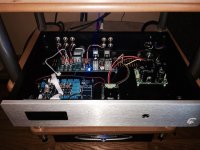
I got the boards all mounted in the chassis. The remote control from Analog Metric runs the Alps pot no problem. I have having issues getting it to control the input relays. The remote board simply switches a transistor to connect the relay - to GND, so I tied the GND's of the Mez and the remote board but when it switches, it blows a fuse on the AC line. I am powering the remote PCB off a 7809 regulator between one set of the secondaries of the same transformer connected to the Mez. Does it matter if it is the positive or negative Mez supply secondary as long as the CT is GND on the 7809?
Attachments
The Mez feeds +12VDC from its 7812 IC reg to all relay coils and a switch simply closes to that feed's return each one selectively. You probably have to separate non correlated returns and only switch to the Mez'z GND (power ground return).
The remote control board is a PIC that is switching a B550 to GND, so I was thinking if I tied the GND of the Mez and the Remote board together, those transistors would power the relay coils on the Mez. At least that was the thought ...
See attached schematic. I am using the Channel Selection outputs to tie into the remote Mez switch locations.
See attached schematic. I am using the Channel Selection outputs to tie into the remote Mez switch locations.
Attachments
Last edited:
I just ordered a Par-Metal 20-series chassis for it. I'm using an MV-04 remote volume kit from ebay to drive a LightSpeed attenuator for it
The Mez is so good, it inspired me to start working on an all wood cover and faceplate and exotic wood knobs, metal bottom and front/rear plate.. Two of these chassis for Mez and one for simplistic RIAA.. Looks pleasing so far..
I'm only using a $3 pot.. Just received Alps rk47, don't know what to expect..
MA500's stay in the home
Last edited:
You should use one or the other power source and control. Not together.
It has to be possible. The audio signal never leaves the Mez board and the controls are simple relays and motorized pot. I see no reason the controls for those devices can't reside off-board. The motor for the volume works fine, I just need to be able to control the relays now.
I tried powering the remote board off of the Mez 12V reg, but it drew too much current and shut down.
Pass DIY Addict
Joined 2000
Paid Member
Craig, I'm working through this same issue right now. My remote control board has volume and switches up to 4 inputs (with mute- which disconnects all inputs). I was looking for a way to remove the relays that came with the remote board and have the remote board directly control the relays on the DCB1, but they use incompatible voltage levels (remote control boards runs on 5V, not enough to drive the 12v relays on the DCB1 board).
So, I will use the relays that came with the remote control unit to replace the rotary switch for input selection on the DCB1. Thus, my build will have 2 sets of relays.
So, I will use the relays that came with the remote control unit to replace the rotary switch for input selection on the DCB1. Thus, my build will have 2 sets of relays.
Cut the +V and ground to the relays from the Mez power and use the controller's?
I thought about that ... the only bad part is the controller is 5V so I would need to replace the relays with a 5V version. They are a pain to replace too as I did one already and did a little damage to the PCB. I was hoping to just find a way to easily tie the grounds of the 2 boards together to just switch them.
- Home
- Amplifiers
- Pass Labs
- Mezmerize DCB1 Building Thread