You
Yes, but no. The transitions all fall on clock edges (quantized) whereas class D transitions are movable in continuous time (analog).
This damned tablet keeps 'correcting' my spelling. I only notice once I've posted it.
This all seems rather Class-D to me. Just duty cycle modulation of a square wave. Low pass filter it to get the audio signal. The audio signal is already there, you just want to get rid of the RF.
This puts an interesting spin on the Power DAC. If you could get the power output stage to switch fast enough, you could use the DSD signal to run the amplifier output stage. Sort of a Class-D direct.
Yes, but no. The transitions all fall on clock edges (quantized) whereas class D transitions are movable in continuous time (analog).
This damned tablet keeps 'correcting' my spelling. I only notice once I've posted it.
Last edited:
You
Yes, but no. The transitions all fall on clock edges (quantized) whereas class D transitions are movable in continuous time (analog).
This damned tablet keeps 'correcting' my spelling. I only notice once I've posted it.
I think there's constant-frequency class D but also constant pulse-width class D, no?
Jan
Yes, in the case of constant frequency one transition is clocked, but the other moves in continuous time. This is also called PWM, and needs to be distinguished from digital PWM. I think (I stand to be corrected here) this arrangement is more commonly encountered in SMPS's, which are amplifiers, like any voltage regulator. Similarly constant pulse-width can be employed with continuously variable frequency, and this is a form of Pulse Density Modulation.
I was just trying to draw a quick distinction for Pano, with reference to self-oscillating types, but in general class D amplifiers have a continuously variable control element as opposed to digital PDM, which is quantized. This is why they can achieve good fidelity at oscillation frequencies that would not be high enough for digital, which I think needs to go to 2.8901376 GHz to get adequate resolution (16/44k1) PWM.
I was just trying to draw a quick distinction for Pano, with reference to self-oscillating types, but in general class D amplifiers have a continuously variable control element as opposed to digital PDM, which is quantized. This is why they can achieve good fidelity at oscillation frequencies that would not be high enough for digital, which I think needs to go to 2.8901376 GHz to get adequate resolution (16/44k1) PWM.
Just ordered a amanero board for usb to dsd.
What will be best for separating board from outputcircuit, transformer or iso7640fm chip?
http://www.ti.com/lit/ds/symlink/iso7640fm.pdf
What will be best for separating board from outputcircuit, transformer or iso7640fm chip?
http://www.ti.com/lit/ds/symlink/iso7640fm.pdf
Thanks Counter Culture, I don't know much about PDM, but am keen to learn.
Still, if the line level device needs only a low pass filter to recover the AF, then wouldn't that be the same with a power device? Of course switching that fast would not be easy, as you point out.
Still, if the line level device needs only a low pass filter to recover the AF, then wouldn't that be the same with a power device? Of course switching that fast would not be easy, as you point out.
DSD power amp
There is an interesting AES paper on this,
"Digital audio power amplifier for DSD data streams" (authors Prime and Hawksford)
It is a digital power amplifier optimized specifically for use with DSD.
Thanks Counter Culture, I don't know much about PDM, but am keen to learn.
Still, if the line level device needs only a low pass filter to recover the AF, then wouldn't that be the same with a power device? Of course switching that fast would not be easy, as you point out.
There is an interesting AES paper on this,
"Digital audio power amplifier for DSD data streams" (authors Prime and Hawksford)
It is a digital power amplifier optimized specifically for use with DSD.
i wonder how those people are doing it?
lector-audio.com/Dot-Bit
the D i g i t u be D S D was 2000 euro should be similary price...
Martin Gagnon
lector-audio.com/Dot-Bit
the D i g i t u be D S D was 2000 euro should be similary price...
Martin Gagnon
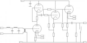
Below my concept for a output filter/buffer schematic. The values will follow later after testing. It is a 24db/oct LP filter at 34khz, transformer decoppling between digital and analog, the tube buffer can also drive headphones and at the and a relaycontact for muting so that there a no strange noises when there is no music playing.
Attachments
Last edited:
Beautiful, be nice to see without the headphone amp, just the tube pre part...
Thanks
Martin Gagnon
Thanks
Martin Gagnon
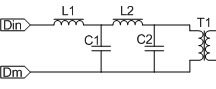
Below my concept for a output filter/buffer schematic. The values will follow later after testing. It is a 24db/oct LP filter at 34khz, transformer decoppling between digital and analog, the tube buffer can also drive headphones and at the and a relaycontact for muting so that there a no strange noises when there is no music playing.
Please keep us updated of your progress. A couple of questions if I may;
why 34KHz? are you assuming minimum rate of DSD128?
How about a TVC instead of the Llundahl?
Ray
Hello Ray,
the crossingpoint is even a little bit heigher, 36,4khz.(butterworth).At that point the frequencycurce at 20khz was only -0.1db lower.
The primary resistance of the transformer needs to be relative high and must be known. This resistance is part of the filter calculation, in this case 1220 ohm.
Until yet this is just a concept.
Waiting for my amareno, other parts i have already. If the concept is proven i will design also a PCB. This PCB will supply several options. Just passive filter or with tube output or opamp output.
Ronny
The primary resistance of the transformer needs to be relative high and must be known. This resistance is part of the filter calculation, in this case 1220 ohm.
I was thinking of the TVCs mentioned at the start of the thread;
SAC Thailand
or these;
SOWTER ATTENUATOR TRANSFORMERS TVC VOLUME CONTROL
Anyway, appreciate your sharing and looking forward to seeing developments.
Today I put together some PC hardware based on a passively cooled Intel Atom processor and a SSD. I've installed AP-Linux and it all seems to be working fine - it seems like a nice package. Now waiting on delivery of a JLSounds USB board, then I'll be able to experiment with a simple filter like Hazard's.
Ray
I also use atom processor itx board from Zotac for several years. Windows 7 OS, foobar with anamon ipad plug in and teamviewer remote software. Also SSD and network storage.
I was thinking of the TVCs mentioned at the start of the thread;
SAC Thailand
or these;
SOWTER ATTENUATOR TRANSFORMERS TVC VOLUME CONTROL
Anyway, appreciate your sharing and looking forward to seeing developments.
Today I put together some PC hardware based on a passively cooled Intel Atom processor and a SSD. I've installed AP-Linux and it all seems to be working fine - it seems like a nice package. Now waiting on delivery of a JLSounds USB board, then I'll be able to experiment with a simple filter like Hazard's.
Ray
Will be very interested, I have a jlsounds board but cant get it to work in this application.
Not sure I follow you here. Doesn't the low pass filter point depend on the impedance it's driving? Meaning the impedance of the circuit following the transformer divided by the transformer ratio and the addition of DCR?The primary resistance of the transformer needs to be relative high and must be known. This resistance is part of the filter calculation, in this case 1220 ohm.
Thanks Gieffe. I will look it up.There is an interesting AES paper on this,
"Digital audio power amplifier for DSD data streams" (authors Prime and Hawksford)

Will be very interested, I have a jlsounds board but cant get it to work in this application.
In what respect can't you get it to work?
Ray
DC resistance must be high enough. otherwise you can destroy or distort the output of the amanero or other source.Not sure I follow you here. Doesn't the low pass filter point depend on the impedance it's driving? Meaning the impedance of the circuit following the transformer divided by the transformer ratio and the addition of DCR?
- Home
- Source & Line
- Digital Line Level
- The Best DAC is no DAC