Hello guys,
I soldered amp as I received and would say made a good job for first smd soldering 🙂. After connecting a lm1084 PSU, I got no sound and nearlly 3.5 V on power inputs of the both amps, tried separately. disconnected PSU gives 24 V. and also tried with 24V notebook PSU which gives 0.5 V on power input connectors while connected.
Can you give any advice how to find problem?
Thanks and best regards
Arda
If you put a voltmeter on the inputs, the input capacitors will pull the voltmeter up to your 3 or so volts.
I can't tell if the diodes are in correctly...white band to white band?
How did you connect your music source?
I can't tell if the diodes are in correctly...white band to white band?
How did you connect your music source?
Hi Doug,
Band of diode is to pcb/white band side.
I connected speaker out from computer with bridging ground and minus on pcb inputs.
Then tried with balanced output from Dac. Tried with working small speaker.
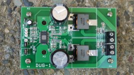
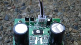
Heat sinks,self stick copper blocks, removed for photo. 1 board shortly powered like 2 seconds before realized I didn't put a heat sink but having the some problem on both.
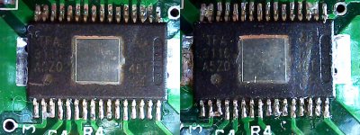
I soldered both amp at the same time. If I made a mistake they would be on both boards I guess. I double checked before proceeding. My only guess would be IC which I was careful on soldering but you never know. How can I check health of it?
Thanks and best regards
Arda
Band of diode is to pcb/white band side.
I connected speaker out from computer with bridging ground and minus on pcb inputs.
Then tried with balanced output from Dac. Tried with working small speaker.
Heat sinks,self stick copper blocks, removed for photo. 1 board shortly powered like 2 seconds before realized I didn't put a heat sink but having the some problem on both.
I soldered both amp at the same time. If I made a mistake they would be on both boards I guess. I double checked before proceeding. My only guess would be IC which I was careful on soldering but you never know. How can I check health of it?
Thanks and best regards
Arda
Attachments
With speaker attached, (always) and with power applied, measure the voltage across the bootstrap caps.
Measure voltage across C4.
Look at IC soldering under X10 and check for shorts...could be small whiskers of solder that are hard to see. You can use liquid solder flux and re-flow each pin to correct. Clean with alcohol after.
Measure voltage across C4.
Look at IC soldering under X10 and check for shorts...could be small whiskers of solder that are hard to see. You can use liquid solder flux and re-flow each pin to correct. Clean with alcohol after.
Don't stress about heatsink, I mostly use 3116 without any heatsink.
You did mount c24 bottomside ?
You did mount c24 bottomside ?
Hi all,
Reflowed the IC pins and used flux (solid) as before. and cleaned with isopropyl alcohol.
c24 is in place, no parts spared or empty exp. r7 c5
on general c04 c12 c14 c15 around 0.8 volt ac, c13 gives 0. And dc readings fall from 0.025v to 0 in seconds. Its not 10/10 times but most readed values.
power inputs constant 0.03 v dc. input from pc reads 0.6-0.3 vac. there is signal.
I will try again when I got a proper notebook psu, mine has noisy fan to give me headache. btw what should I read for measurements.
Thanks
Arda
Ok, new notebook psu and all working as intended 😀
Don't lose time with cheap smps, why guy didn't tell he got what I asked before 🙂
Thank Doug and all. Didn't measure all but caps but some read 6 vdc.
Best regards
Arda
Don't lose time with cheap smps, why guy didn't tell he got what I asked before 🙂
Thank Doug and all. Didn't measure all but caps but some read 6 vdc.
Best regards
Arda
More boards available ?
I just stumbled upon this thread. Do you have any more boards available ? If so, I'll take a few...
As of 20 June 2015 (1 year anniversary) this buy will close.
I only have boards left.
I just stumbled upon this thread. Do you have any more boards available ? If so, I'll take a few...
I just stumbled upon this thread. Do you have any more boards available ? If so, I'll take a few...
They are in pairs but I can cut them into singles if you would like them that way.
Still $8 CDN per board plus postage.
Where are you?
They are in pairs but I can cut them into singles if you would like them that way.
Still $8 CDN per board plus postage.
Where are you?
I'm right here in Ottawa, Ontario. I'll take 4, you don't have to cut them.
I'm right here in Ottawa, Ontario. I'll take 4, you don't have to cut them.
Fantastic.
2 pair 4 x 8 $32
postage $6
Total $38
PM your e-mail for paypal invoice. (and your mailing address if not in paypal)
Help and Recommendation
Whew, it took a while, but I finally got the board populated (with supplied kit) with the help of my brother-in-law, who solder SMD for a living. From what I can tell, he did a professional job. What do you think? Does it look like he installed the parts correctly?
He did install a Molex header (0022112032) for J1, J2, and J3 (per Dug's BOM). But before I can mount these boards in a case, I need help from our gracious and experienced (or knowledgable) member of this forum (or Dug if he could chime in). Here are my questions:
1) Where can I buy the female connector for J1, like the one shown in the picture, with wires already attached (3 wires, for ground, "+", and "-")? The one I have came from the YJ Blue board. I tried browsing Mouser and Digikey but cannot find it. Their site has millions of parts. Is it under Connector or something else? I rather have a connector installed than soldering the wires directly.
2) I am thinking of ordering better inductor (L1 and L2), together with other parts I am ordering to save shipping, in case the sound of the stock part is not to my liking. Any recommendation? Dug used Wurth on his build, while others used Coilcraft of other values. I have zero knowledge and do not have experience on modifying these parts, I hope you can give me guidance.
3) Is it beneficial to replace the power supply bypass caps (C6 and C7) with different brand or value?
My current setup is: Computer (Windows 8, JRiver)>Emotiva XDA-2 USB>YJ 6N3 tube preamp>YJ Blue Board>DIY Speaker (8-ohm, 89db, 2-way, Dyna Audio drivers). The XDA-2 will be replaced by Emotiva DC-1 in the near future.
Any help will be appreciated. Thanks!
Attachments
As a folow up, my other question is in regard to J1. How do you connect the "ground" and the "-" of the board to RCA of case's panel? Do you connect it together, then run it to negative of RCA? As far as I know, input has only negative and positive (no ground).
1. IDC connector like these:
Rectangular Connectors - Free Hanging, Panel Mount | Connectors, Interconnects | DigiKey
You can solder to them if you are quick and don't let the solder run down the connector. Put some solder on the wire and some solder on the IDC area and then solder solder to solder.
2 See my list in the first post...or go through all of this thread, gmarsh GB thread and the TPA3116 thread...lots of opinions.
3 I don't think so but others have found some "OSCON" caps that they prefer.
Read the data sheets of the supplied caps and any you are thinking of using...look at ESR (equivalent series resistance) (lower the better) and ripple current (the higher the better)
Follow up question
Connect the + to signal source +.
Connect the - to signal source gnd.
Connect the board gnd to signal source gnd.
Soldering looks very good.
Thanks for the response, Dug. It is a big help.🙂
I have additional questions, if you do not mind:
1) If I want to use one power switch for both boards (one Astron RS-7A), can I use the "sync" (J5) for this purpose, or is it for something else? I have another Astron 7A that I could use if I decided to have a dedicated power supply for each board (if SQ will be better).
2) I understand that any brand of inductors listed in the BOM (or used by others in this thread) is a step up in SQ over the stock version?
3) I am inclined to use Wurth (same as yours) for the inductor. Any thoughts as to how it differ ( as far as SQ is concern) from the stock? I would like to squeezed out as much SQ for this board. I will be using Emotiva DC-1 DAC for this setup.
Thanks a lot!
1. IDC connector like these:
Rectangular Connectors - Free Hanging, Panel Mount | Connectors, Interconnects | DigiKey
You can solder to them if you are quick and don't let the solder run down the connector. Put some solder on the wire and some solder on the IDC area and then solder solder to solder.
2 See my list in the first post...or go through all of this thread, gmarsh GB thread and the TPA3116 thread...lots of opinions.
3 I don't think so but others have found some "OSCON" caps that they prefer.
Read the data sheets of the supplied caps and any you are thinking of using...look at ESR (equivalent series resistance) (lower the better) and ripple current (the higher the better)
Follow up question
Connect the + to signal source +.
Connect the - to signal source gnd.
Connect the board gnd to signal source gnd.
Soldering looks very good.
1. The sync function is for the switching frequency. To use one switch for two independent supplies/amps you can use a double pole switch. (DPST or DPDT)
2. Not necessarily. Look at the L vs I curve, DC resistance and the self resonance frequency.
Try a few different ones. These boards were made for experimentation.
3. I have only tried 3 types of inductors on 3 different boards:
DUG-0 (demo at Toronto get together a few years ago and a blank board sent to xrk971 early in the TPA3116 thread)
DUG-1 (This GB and my main home stereo amp and the sub in the Boombox)
DUG-3 (used in Boombox...thread in "full range" forum)
I can't say that there is much difference because I did not do an A / B test.
I do believe that this amp sounds best and has less noise with a low impedance drive.
So I recommend a buffer for your DAC if it does not have a low Z output impedance.
Last edited:
I have some cases on the way and thinking about board layout.
Will pair the DUG with a Connex SMPS + stepped attenuator in one box, keeping things as compact as possible.
Below is a cutout of the case internal footprint. Attenuator will go on the front panel in the open space at the lower right corner. Any suggestions for how to position the 100x100mm SMPS? What can I expect to be the "noisiest" edges to keep far away from the DUG? I've already located the DUG inputs at the far right edge.
BK
An externally hosted image should be here but it was not working when we last tested it.
Nice build bk586er.
Done my build and powered up today. Must say, I'm impressed. 🙂
Sounds very transparent. The LF response is better than quite a few of the Class-D amps I've tried out. Using Coilcraft inductors, ~20V power (15v toroid). The C6 and C7 caps I am using are rated 2200uf - too much?
Done my build and powered up today. Must say, I'm impressed. 🙂
Sounds very transparent. The LF response is better than quite a few of the Class-D amps I've tried out. Using Coilcraft inductors, ~20V power (15v toroid). The C6 and C7 caps I am using are rated 2200uf - too much?
- Status
- Not open for further replies.
- Home
- Group Buys
- GB for TPA3116/8 PBTL bare pcb