P.S. I can find you Raw DC with snubbers on DertyPCB. Is it ready?
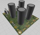
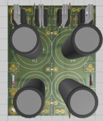
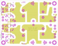
5x5 Raw DC board is temporarely on hold, working on something little bigger, 10x8 indepedent 2 channel Raw DC CR(L)C (configurable as dual rail symetric).
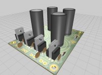
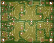
3D rendering is only aproximation.
===========================================
Final version is at http://www.diyaudio.com/forums/powe...raw-dc-board-cr-l-c-filter-4.html#post4329885.
Boards are available at Raw DC@Dirt Cheap Dirty Boards.
Attachments
Last edited:
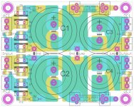
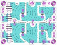
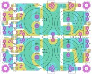
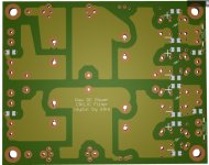
Interesting routing details:
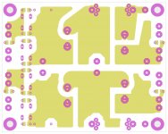
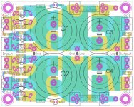
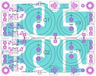
- Input(charging) and Output(discharging) traces of big filter capacitors are routed on diferent layers, this way separated charging&discharging currents
- Complementary signals routed on adjacent traces (above/below each other)
- From Input to Output, signals change layers, top-bottom-top or bottom-top-bottom , to simulate "twisted pair effect", reducing EMI interference&radiation
Could the back to back diode rectifiers short together?
Yes, insulator is absolutely necessary between diodes, but with insulator sheet between and non conductive screws, diodes mounted as pairs are mechanically much better mounted to the board, no more bending side to side.
I have some chinese boards with TO-220 diodes mounted alone, and it is so easy to bend diodes side to side.
Is this for a power amp or such use, with the TO-220 diodes, sikahr?
Alex, which board at 'DirtyPCB' have you found?
Alex, which board at 'DirtyPCB' have you found?
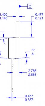
Distance between diode pair center of the pins is cca 7mm,
diode side depth (MUR860) from center of the pins to back of the diode is 2.7-3 mm, so remaining space is 1-1.5 mm,
i believe enough for insulator sheet (it seems that standard silicon insulator sheet depth is 0.3 mm - source ebay 🙂 )
diode side depth (MUR860) from center of the pins to back of the diode is 2.7-3 mm, so remaining space is 1-1.5 mm,
i believe enough for insulator sheet (it seems that standard silicon insulator sheet depth is 0.3 mm - source ebay 🙂 )
Attachments

Is this for a power amp or such use, with the TO-220 diodes, sikahr?
Alex, which board at 'DirtyPCB' have you found?
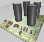
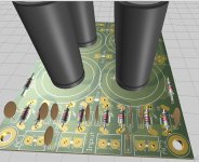
Well, capacitors max diameter, C1&C2 35mm, C3&C4 30mm,
so this board can give some current, but maybe not enough for full power amp, maybe used in pairs with mono blocks.
TO-220 are here mostly because of space considerations, taking vertical space only, you can use other diode packages (which will fit mounting holes) for low power.
This supply is overkill for preamp or similar low power loads, but this is DIYaudio, overkill is expected here, why not?
Large capacitance filtering is superior to small capacitance.
With the diode tabs so close, will convection be effective in removing heat from the rectifiers? And if you join them, then you effectively lose most of the surface area of the package that allows it to dissipate heat. You now have 2 power rectifiers hooked together with their ability to dissipate heat stunted.
With the diode tabs so close, will convection be effective in removing heat from the rectifiers? And if you join them, then you effectively lose most of the surface area of the package that allows it to dissipate heat. You now have 2 power rectifiers hooked together with their ability to dissipate heat stunted.
All true if you go for max Ampers.
This type of diodes are specified to cca 8 A, and I am planing to use it to max 1-1.5A, so I dont believe heat will be problem for low to moderate load.
For poweramp, better to use large 25A external bridge rectifiers (two, one per channel), bring DC to board and put jumpers accross diode placeholders ( 4 jumpers, 4 empty).
Last edited:
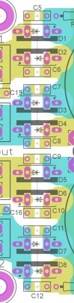
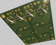
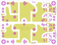
Board & 3 different diode packages possible:
- TO220 (MUR8XX&similar)
- small diodes DO41 (1N41XX&similar)
- DO201 (1N54XX&similar)
Resistors represent diodes on 3D pictures
- TO220 (MUR8XX&similar)
- small diodes DO41 (1N41XX&similar)
- DO201 (1N54XX&similar)
Resistors represent diodes on 3D pictures
Attachments

Is this for a power amp or such use, with the TO-220 diodes, sikahr?
Alex, which board at 'DirtyPCB' have you found?
I couldn’t find Raw DC presented by Sikahr earlier. I assumed it is already there.. I understood why it is no there after he explained. I like his new board better, at least for no SMD parts involved and mainly for its flexibility. I’ll wait patiently when it will be at DetryPCB. Definitely going to use it for low current builds.
Ah sikahr, there it is - nice bit of flexibility on the AC input side
A couple of points to highlight a different approach to this end of the supply - not sure how useful it might be
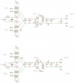
C1, C2 are the 'ripple caps - the usual design spec asks for twice the capacitance at C3, C4 so I would change the sizes allocated and this also allows P1/P2 & P3/P4 to move beside the C1, C2 caps - R3 & R4 are better on the outputs after C3 and C4 - discharge resistors? I often add small size leds to show this part of the supply is energized
I suggest seriously deleting all the caps across the diodes - they allow high freq noise to directly bypass the diodes - in their place fit the snubbers (R + C //C) across each input secondary winding
The diodes produce current pulses, quite high even for low power supplies, so better to avoid the 'semi-planar' slabs of copper and use simple thick tracking in this area and, if possible, avoid the use of vias on electro caps ( convenient, but awful practice) and also the double sided tracking -
A lot of people will disagree with this, mentioning all sorts of benefits and, no doubt, quite reasonable too, but the 100Hz (120 in US) high current pulses need no assistance in broadcasting noise and 'stuff' across the board - better to restrict it with short direct heavy duty tracks as far as possible.
Something unrelated here but I think relevant - the ripple caps C1 & C2 are selected to withstand the 'current pulse beatings' that is their job in life - some of our usually recommended caps are good at this, but quite a few are the cause of a loss of performance here - all sorts of opinions abound in this ...
The second caps, C3 & C4, are the power caps and the Duncan design recommends they be twice the capacity of the 'first' caps - they are also selected for the different job that they do, supplying current to the active circuit - these may have different pin spacings
Most people just select the 4 caps of the same make, size, etc for cost/performance
Is all this at all relevant considering the following high quality filters? On a high resolution system, headamp, etc, it's easy to hear the difference but some people don't think the bother is worth it - those various opinions again.
Anyhow, perhaps this maybe of use, but also maybe irritant - not intended, I assure you.
... regards
A couple of points to highlight a different approach to this end of the supply - not sure how useful it might be
C1, C2 are the 'ripple caps - the usual design spec asks for twice the capacitance at C3, C4 so I would change the sizes allocated and this also allows P1/P2 & P3/P4 to move beside the C1, C2 caps - R3 & R4 are better on the outputs after C3 and C4 - discharge resistors? I often add small size leds to show this part of the supply is energized
I suggest seriously deleting all the caps across the diodes - they allow high freq noise to directly bypass the diodes - in their place fit the snubbers (R + C //C) across each input secondary winding
The diodes produce current pulses, quite high even for low power supplies, so better to avoid the 'semi-planar' slabs of copper and use simple thick tracking in this area and, if possible, avoid the use of vias on electro caps ( convenient, but awful practice) and also the double sided tracking -
A lot of people will disagree with this, mentioning all sorts of benefits and, no doubt, quite reasonable too, but the 100Hz (120 in US) high current pulses need no assistance in broadcasting noise and 'stuff' across the board - better to restrict it with short direct heavy duty tracks as far as possible.
Something unrelated here but I think relevant - the ripple caps C1 & C2 are selected to withstand the 'current pulse beatings' that is their job in life - some of our usually recommended caps are good at this, but quite a few are the cause of a loss of performance here - all sorts of opinions abound in this ...
The second caps, C3 & C4, are the power caps and the Duncan design recommends they be twice the capacity of the 'first' caps - they are also selected for the different job that they do, supplying current to the active circuit - these may have different pin spacings
Most people just select the 4 caps of the same make, size, etc for cost/performance
Is all this at all relevant considering the following high quality filters? On a high resolution system, headamp, etc, it's easy to hear the difference but some people don't think the bother is worth it - those various opinions again.
Anyhow, perhaps this maybe of use, but also maybe irritant - not intended, I assure you.
... regards
James, thanks for your opinion and advice.
I allready added transformer snubbers, but i think better not to delete caps across the diodes, this way user have flexibility and may use whatever want, transformer "Hagerman" snubbers, diode snubbers, both, or nothing, user have total control.
Regarding power track routing, I will repeat:
Routing details:
- Input(charging) and Output(discharging) traces of big filter capacitors are routed on diferent layers, this way separated charging&discharging currents
- Complementary signals routed on adjacent traces (above/below each other)
- From Input to Output, signals change layers, top-bottom-top or bottom-top-bottom , to simulate "twisted pair effect", reducing EMI interference&radiation
I am not sure this is the best way but I believe is worth trying, there are many other boards routed strightforward from input to output, this one is different, for worse or better (better I hope 🙂 ).
Regarding C1-C4 sizes, capacitors max diameters are, C1&C2 35mm, C3&C4 30mm, pin spacing is combined 10mm&7.5mm for C1-C4. I hope this is good enough for different user configuration.
If you think additional pin spacing or pin position is needed, please advice me with some examples.
Regarding discharging resistors&LED, I think connection point of discharging resistors (C1&C2 or C3&C4) is not important, they will do their job regardless. I will try to add LEDs.
No problems - most of my 'natter' should be regarded as "considerations" only as we all have different systems and different ideas - the board seems to have included most options especially discrete diode (don't like the GB bridges at all!)
Will this board fit into the next size for DirtyPCB - the $25 package? I can't believe these low prices
Thanks ... James
Will this board fit into the next size for DirtyPCB - the $25 package? I can't believe these low prices
Thanks ... James
Will this board fit into the next size for DirtyPCB - the $25 package? I can't believe these low prices
Yes, 10x8 cm, 25$, 10+- pieces, not bad LOL
Yes, 10x8 cm, 25$, 10+- pieces, not bad LOL
It is the same price as for 10cmX10cm and it is creating possibility to add K-Multiplier to the same beard with Raw DC. How about that idea?
If yes, it should be two positive K-Multy connected or not connected, and depend to dual positive or dual polarity setup.
Last edited:
More or less finished, speak now or never
I can't resist an invitation like that!
I would like to see a way to insert another resistor in the ground track between the caps but I can't see anyway amongst the overlapping layers (the current pulses travel thru the ground return track too and this helps get the 'ground noise' down - old idea)
Similarly, no provision for a resistor between the diodes and the first cap, including the ground track - this reduces the current pulse/voltage spikes and increases the charging conduction angle of the first cap - can use the 3W SMD resistors underneath...
Just details, and possibly of no great interest, but there is a spare 20mm available ...
Snubber Cap size: If we use the Haggerman snubber version and test with the Quazimodo, these will be 10nF and 150nF - allowed space is only about 7mm (restricts the type of caps used - can maybe tack bigger ones on below, I suppose).
What is a concern is the tiny donuts for the resistors - possibility of changing these is high but these donuts won't survive many changes - there's room for much bigger ones
Can add the discharge resistors underneath, unless I've missed them?
I assume the C13, 14 on the output are those little 1837 caps that the 'Handmade' guy recommends? They're about 7 x 4mm, I think.
Don't think you'd ever need a bigger diameter cap for C1/C2 than C3/C4, even if you use 'low etch depth' caps for the C1/C2 - can save some space there.
All the best ...
Hi,
James&Alex thanks for your input.
Regarding using 10x10 PCB instead of 10x8, I am afraid it is not possible for me because for drawing PCB I use free version of Eagle PCB which have limitation to 10x8, sorry 🙁.
Regarding other suggestions I will answer latter, don't have time now.
Thanks, sika
James&Alex thanks for your input.
Regarding using 10x10 PCB instead of 10x8, I am afraid it is not possible for me because for drawing PCB I use free version of Eagle PCB which have limitation to 10x8, sorry 🙁.
Regarding other suggestions I will answer latter, don't have time now.
Thanks, sika
- Status
- Not open for further replies.
- Home
- Amplifiers
- Power Supplies
- 10x8 Raw DC board with CR(L)C filter