Yes that is the precision to expect. Most of the deviation at the highest frequency will be due to inadequate resolution and/or inadequate boundary conditions such as the exit condition being too close or too reflective. It is normal in 3D simulations for the highest frequencies to be a bit off because of the high computational cost of using fine grids leading to the grids being on the under resolved side. The quoted 6 elements per wavelength looks a bit optimistic to me if they are using tetrahedral elements and lowish order finite elements. Similarly exit conditions tend to be pulled a bit too close to the working section in order to reduce the grid size.I guess this is the sort of precision that is obtainable with this process:
How about the very small simulated volume. Do they not care about diffraction at the mouth?Yes that is the precision to expect. Most of the deviation at the highest frequency will be due to inadequate resolution and/or inadequate boundary conditions such as the exit condition being too close or too reflective. It is normal in 3D simulations for the highest frequencies to be a bit off because of the high computational cost of using fine grids leading to the grids being on the under resolved side. The quoted 6 elements per wavelength looks a bit optimistic to me if they are using tetrahedral elements and lowish order finite elements. Similarly exit conditions tend to be pulled a bit too close to the working section in order to reduce the grid size.
Or are they using a calculated far field solution?
/Anton
STLs for 1" CDs
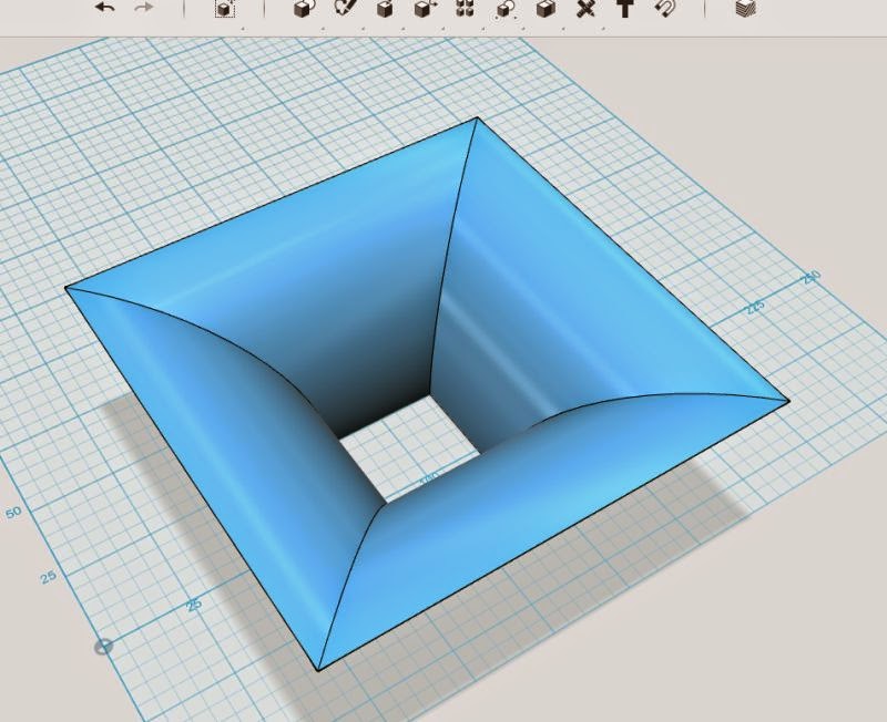
xrk was asking for a STL for 1" compression drivers. Here's a few 90x60 horns that have the following parameters:
W_total: 210 mm
H_total: 130 mm
D_total: 95 mm
R_throat: 12.7 mm
R_vert: 20 mm (vertical roundover at mouth)
R_hor: 50 mm (horisontal roundover at mouth)
Alpha_vert: 30 degrees (vertical coverage = 60 degrees)
Alpha_hor: 45 degrees (vertical coverage = 90 degrees)
N: 1.5 (superellipse)
The geometry has been simplified according to suggestions from andy19191. The mounting holes are 76 mm apart and 6.5 mm diameter (should suit M6). Calculated printing time for 3 shells and 30 % fill is 5.5 hours with my printer.
The throat angle differs according to file name.
7 deg should suit BMS 4550 and B&C DE250.
12 deg should suit CDX1-1445, CDX1-1440, BMS 4552, B&C DE12.
I have not tried printing any of these. I recommend low printing speed for the first layers as the overhang angle is large initially but will quickly decrease.
I can easily make other similar waveguides (other dimensions or angles), just ask me if you feel like printing one 🙂
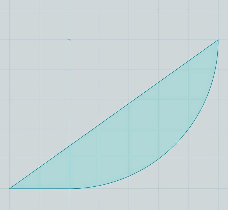
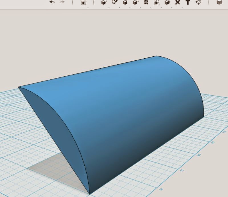
Here is what the geometry looks like:


/Anton
xrk was asking for a STL for 1" compression drivers. Here's a few 90x60 horns that have the following parameters:
W_total: 210 mm
H_total: 130 mm
D_total: 95 mm
R_throat: 12.7 mm
R_vert: 20 mm (vertical roundover at mouth)
R_hor: 50 mm (horisontal roundover at mouth)
Alpha_vert: 30 degrees (vertical coverage = 60 degrees)
Alpha_hor: 45 degrees (vertical coverage = 90 degrees)
N: 1.5 (superellipse)
The geometry has been simplified according to suggestions from andy19191. The mounting holes are 76 mm apart and 6.5 mm diameter (should suit M6). Calculated printing time for 3 shells and 30 % fill is 5.5 hours with my printer.
The throat angle differs according to file name.
7 deg should suit BMS 4550 and B&C DE250.
12 deg should suit CDX1-1445, CDX1-1440, BMS 4552, B&C DE12.
I have not tried printing any of these. I recommend low printing speed for the first layers as the overhang angle is large initially but will quickly decrease.
I can easily make other similar waveguides (other dimensions or angles), just ask me if you feel like printing one 🙂
Here is what the geometry looks like:
/Anton
Attachments
Wow, not having a background in acoustics and not having read up much on this stuff I'm kinda over my head when it comes to figuring out the desired shape. I was just hoping to help out with the modeling.
Onni,
If you just want to control the angle of the surface to the end of the throat (@x=0), SolidWorks can actually handle this very well. Part of the loft feature is the option to constrain the angle of the surface to the profile. In this case I just tell SolidWorks to make it perpendicular, and the surface is constrained to 0° around the throat. I'm not sure this will help you though. I'm not familiar enough with the CAD packages you're using. If it helps, I'd be happy to generate solids to your specifications in any file format you like.
I am not sure I fully understand the questions.How about the very small simulated volume. Do they not care about diffraction at the mouth?
Or are they using a calculated far field solution?
If we look at slide 20. The volume is a quarter of the waveguide because of symmetry which introduces no approximations. The edge at the mouth is included without approximation if the Perfectly Matched Layer (PML) is far enough away not to influence the solution gradients at the edge. It looks a bit close to me at the corner of the waveguide.
The PML exit condition is like the absorption on the walls of anechoic chamber. The idea is that all waves leaving the solution region enter the PML without any reflection (Perfectly Matched) and then are rapidly absorbed within the layer. In practise some is reflected on entry and some is reflected back from the inside the layer but this is typically very small.
The far field solution is one of the main things the simulation is trying to determine and so imposing it would be rather counter productive. What the exit condition is striving to do is to let all the outgoing sound waves pass through without reflecting any. It is possible to do this exactly at least for some numerical schemes but the computational cost is much larger than calculating the whole of the internal solution region. So approximate exit boundary conditions are used instead of which PML is one example.
I think it was probably someone else. The only suggestion I recall making about your CAD models was to use a lot more and irregular triangles in the STL files.The geometry has been simplified according to suggestions from andy19191.
That's useful for when you want 0 degrees at the throat entrance. Most of the time that is not the case. Do you have the option to set a specific angle other than 90 degrees (perpendicular)?Wow, not having a background in acoustics and not having read up much on this stuff I'm kinda over my head when it comes to figuring out the desired shape. I was just hoping to help out with the modeling.
Onni,
If you just want to control the angle of the surface to the end of the throat (@x=0), SolidWorks can actually handle this very well. Part of the loft feature is the option to constrain the angle of the surface to the profile. In this case I just tell SolidWorks to make it perpendicular, and the surface is constrained to 0° around the throat. I'm not sure this will help you though. I'm not familiar enough with the CAD packages you're using. If it helps, I'd be happy to generate solids to your specifications in any file format you like.
I have the same option (perpendicular), but not arbitrary angle.
/Anton
Sorry, the suggestion came from rasputin1. I have increased the amount of triangles a lot though 🙂I think it was probably someone else. The only suggestion I recall making about your CAD models was to use a lot more and irregular triangles in the STL files.
/Anton
That's useful for when you want 0 degrees at the throat entrance. Most of the time that is not the case. Do you have the option to set a specific angle other than 90 degrees (perpendicular)?
I have the same option (perpendicular), but not arbitrary angle.
/Anton
Ok, I didn't know that. I can give a directional vector, but it doesn't apply it radially. I'll look into it and let you know when I have it solved (I think I have a trick I can use that will be easy enough). Can you tell me how you would modify the SEOS curves we've been using to get the desired throat entrance angle? The two sets of orthogonal curves are sufficiently different that to start at a different angle needs more modification than just starting at greater than x=0. Or would you model it a different way?
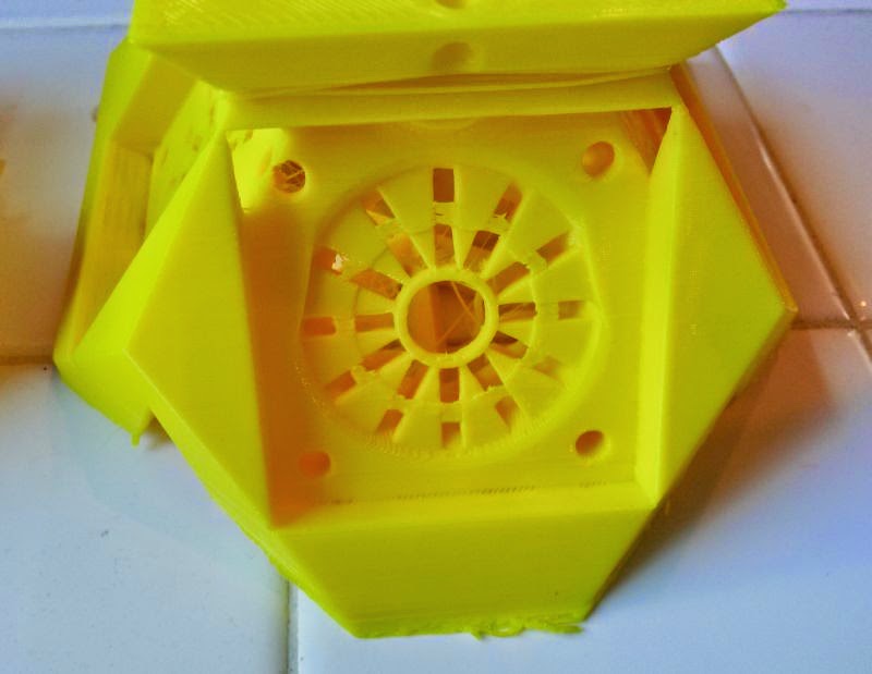
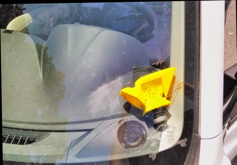

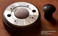
^^ some pics of the latest wg for my car
it features:
1) the same midrange section that Bill Waslo is using in his Synergy horns
2) full-on tangerine phase plugs for all the midrange drivers
3) a waveguide profile swiped from the JBL M2 speakers
More details here:
28 Weeks Later - Car Audio | DiyMobileAudio.com | Car Stereo Forum
That's useful for when you want 0 degrees at the throat entrance. Most of the time that is not the case. Do you have the option to set a specific angle other than 90 degrees (perpendicular)?
I have the same option (perpendicular), but not arbitrary angle.
/Anton
Ok, I can do it with arbitrary angles. I have to create a "pre-throat" section with the desired angle, then I can set the loft to be tangent to the pre-throat. After the loft is created, I just cut off the pre-throat and it's done.
Ok, I didn't know that. I can give a directional vector, but it doesn't apply it radially. I'll look into it and let you know when I have it solved (I think I have a trick I can use that will be easy enough). Can you tell me how you would modify the SEOS curves we've been using to get the desired throat entrance angle? The two sets of orthogonal curves are sufficiently different that to start at a different angle needs more modification than just starting at greater than x=0. Or would you model it a different way?
If you can live with a rectangular mouth, you can achieve the result like this:
1) make the shape in 2D
2) extrude the 2D shape into 3D
3) array the 3D shape around a rectangular throat that's 70% of what you want. IE, if you want a 1" throat that's circular, start with a 0.707" throat that's square
4) and then plunge 1" cylinder through the 0.707" square throat
Very interesting topic on infill feature and web structures. We should try it down to compresion driver membrane. I have to learn 3D print - have an access to Zortrax M200. Usually I use Solidworks.
Very interesting topic on infill feature and web structures. We should try it down to compresion driver membrane. I have to learn 3D print - have an access to Zortrax M200. Usually I use Solidworks.
Once you can make a phase plug, there's really nothing to stop you from making your own compression drivers...
The tangerine phase plug is pretty neat.
I was able to get a very close match to the hornresp prediction using it
Instructions on how to make it are in that link at diyma
For the people who don't have a 3D printer, you could probably print a phase plug for about $20 at shapeways
I was able to get a very close match to the hornresp prediction using it
Instructions on how to make it are in that link at diyma
For the people who don't have a 3D printer, you could probably print a phase plug for about $20 at shapeways
Nice solution!Ok, I can do it with arbitrary angles. I have to create a "pre-throat" section with the desired angle, then I can set the loft to be tangent to the pre-throat. After the loft is created, I just cut off the pre-throat and it's done.
/Anton
This method does however leave us with the task of smoothing the transition from cylinder to profiles.If you can live with a rectangular mouth, you can achieve the result like this:
1) make the shape in 2D
2) extrude the 2D shape into 3D
3) array the 3D shape around a rectangular throat that's 70% of what you want. IE, if you want a 1" throat that's circular, start with a 0.707" throat that's square
4) and then plunge 1" cylinder through the 0.707" square throat
I think that you either go with a fully mathematical definition or something like me and MuddJester have been discussing. However, as has been said, the SEOS-profile is not some holy grail here. It's a very good (one of the best), but when it comes to 3D-printing we have the possibility to tailor a waveguide to a driver/tweeter.
/Anton
- Home
- Loudspeakers
- Multi-Way
- 3D-printing